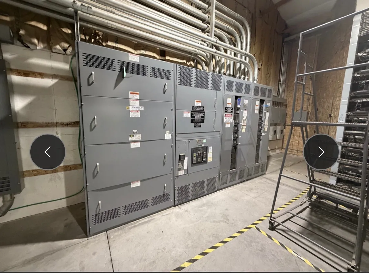
277/480 V Motor Control Centers for Nevada Facilities
A 277/480 V motor control center (MCC) groups motor-control units and related distribution equipment in an assembly configured for a project’s electrical system. At this stated voltage, the distinction between line-to-line and line-to-neutral use matters: three-phase motors commonly connect line-to-line, while compatible 277 V lighting loads may connect line-to-neutral. The actual system arrangement, grounding method, available conductors, and equipment ratings must be confirmed from the project documents. The voltage designation alone does not establish the MCC’s current rating, short-circuit rating, construction, or suitability for a particular installation.
We manufacture new custom power-distribution equipment in the United States using all-American components, with shipping available nationwide, including to Nevada. A project’s facility conditions and installation constraints can influence the design: consider available electrical-room space, access for cable entry and maintenance, environmental conditions, and the route from the source to the MCC. These details should be reviewed with the project’s qualified electrical engineer and equipment documentation before a configuration is finalized.
Motor Starters and VFD Integration — Motor Control Centers for 277/480 V
Starter selection depends on the motor and the way the load operates. A project may call for across-the-line starters, reduced-voltage starting, variable frequency drives (VFDs), or a combination of unit types. Relevant inputs include motor nameplate data, load characteristics, starting frequency, control requirements, and the expected method of operation. A VFD can support adjustable motor speed, but its application involves more than fitting a drive into an MCC: drive selection, protection, heat dissipation, wiring, and compatibility with the motor and driven equipment all warrant engineering review.
Define interfaces early. Identify whether control signals originate locally or from a supervisory system, what feedback is needed, and how the unit interfaces with the facility’s control scheme. The required control power, communications, and terminal arrangements should be described in the project documents rather than assumed from the 277/480 V designation. For VFD units, provide the drive requirements and any specified input or output components so the proposed assembly can be checked against the application and available configuration.
Feeder Protection and Short-Circuit Ratings
MCC feeder units serve loads such as motors, lighting distribution, and other equipment, but they do not all call for the same protective device or setting approach. Feeder protection must suit the connected load and conductor arrangement while coordinating with upstream and downstream devices. Provide the one-line diagram, load information, source details, and available fault-current data when requesting a configuration. Qualified engineers should assess the protective-device selections and coordination for the actual system; a voltage label is not a substitute for that study.
Short-circuit ratings describe an assembly’s ability to withstand or interrupt fault conditions as specified for the equipment. They are distinct from nominal system voltage and must be evaluated against the available fault current and protection scheme at the installation point. Confirm the proposed rating, applicable device combinations, and any conditions or limitations in the equipment documentation. Do not infer a rating from the enclosure, bus arrangement, or a similar-looking MCC.
Line-to-Line, Line-to-Neutral, and Neutral Design
In a 277/480 V system, line-to-line and line-to-neutral connections serve different loads and involve different circuit conductors. A motor feeder may use the phase conductors required by its motor and starter, while a compatible lighting feeder may use a line and neutral. Not every load is suitable for either connection, and the nominal voltage does not establish that a neutral is present at each MCC section or feeder.
State which loads require neutral connections, their expected loading, and how the neutral is to be distributed. Neutral sizing should be determined from the load characteristics and applicable design requirements, including the nature of any nonlinear loads, by the project’s qualified electrical professionals. Clarify whether lighting distribution is part of the MCC scope or served by separate equipment. These choices affect the assembly’s conductor and bus arrangements and should be resolved before design details are approved.
UL 845, Documentation, and Project Verification
UL 845 is a standard associated with motor control centers. Whether it is required for a particular project, and whether a specific offered assembly carries an applicable listing, must be confirmed from the project specification and equipment documentation. Do not assume that every MCC is listed, or that a listing for one product category covers other switchgear or distribution products. Applicable standards, listing requirements, and permitted configurations should be identified during the specification review.
Before an order is defined, verify the service voltage and system arrangement, bus and feeder needs, starter and VFD unit mix, control interfaces, short-circuit requirements, and requested documentation. Confirm all ratings and configuration details against the final equipment documents. Site conditions and electrical design remain subject to review by qualified engineers and other responsible project professionals.
Information That Helps Define an MCC Configuration
A useful quotation package includes the one-line diagram, equipment schedule, motor list with nameplate information, lighting and other feeder loads, source and available fault-current data, and the required control and communication interfaces. Include any project-specific standard or listing requirement, installation constraints, and details about cable entry and maintenance access. This information helps establish what configuration is available and which ratings need confirmation; it does not replace engineering coordination or site review.
For Nevada installations, coordinate shipment and site readiness with the project schedule and receiving plan rather than relying on an assumed delivery date. Confirm that the equipment dimensions and access provisions suit the intended electrical space, and resolve routing and connection requirements before installation planning is complete. Final suitability depends on the documented assembly, the facility’s electrical system, and review by the project team.