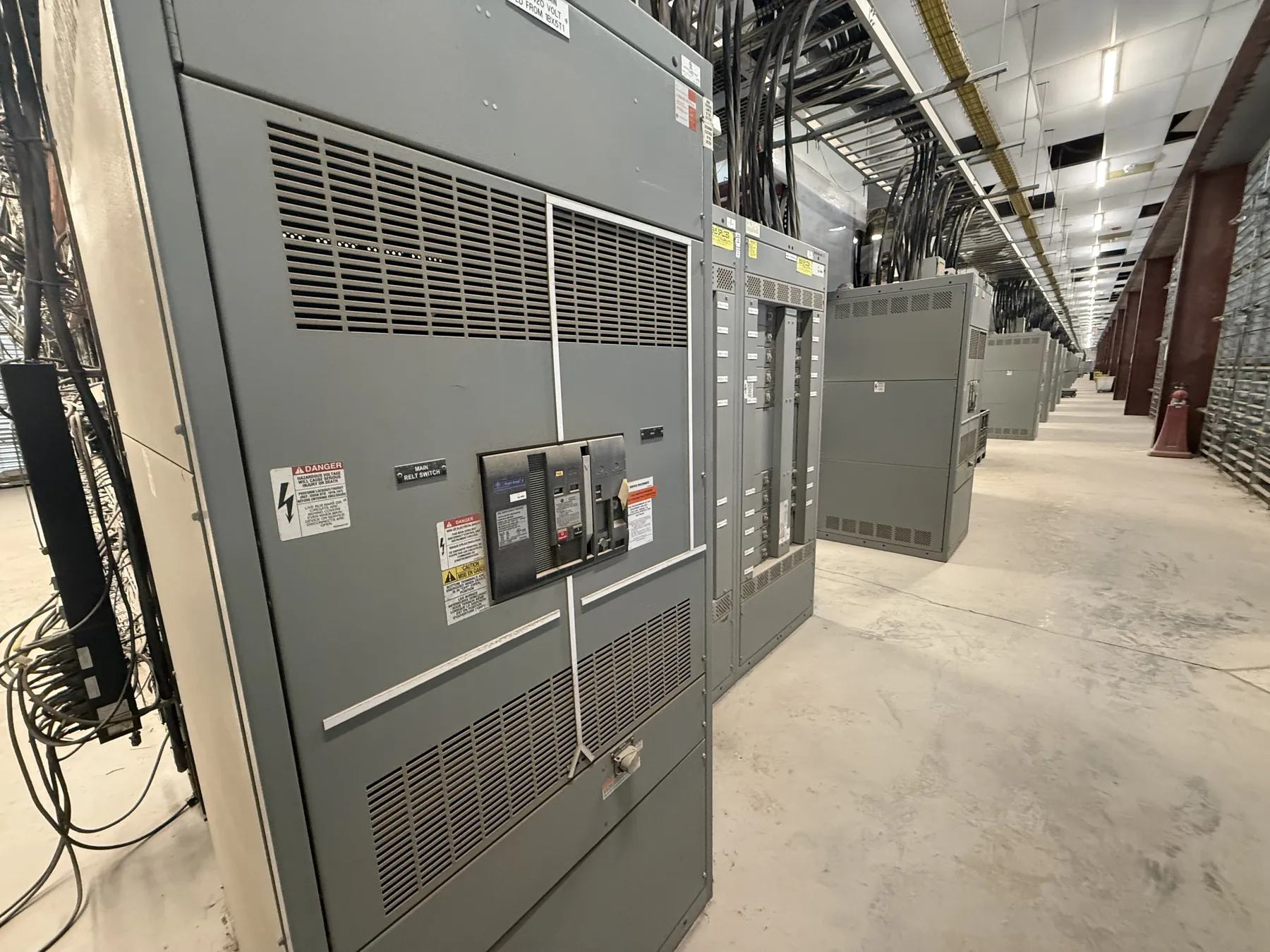
1200 A Motor Control Centers: Start With the Continuous-Current Requirement
A 1200 A motor control center (MCC) is a specified assembly rating, not a statement that every section or motor starter can carry 1200 A. The rating must suit the lineup’s intended continuous-current duty and the way loads are distributed among its sections and vertical buses. Confirm the required rating against the load schedule, expected operating conditions, and equipment documentation—not just the sum of motor nameplate currents.
Ambient conditions matter. Installation location, ventilation, enclosure arrangement, and other site conditions can affect the equipment’s suitability for the application. Anticipated load growth also deserves an explicit decision: spare physical space does not necessarily mean spare electrical capacity. A qualified electrical engineer should evaluate the actual loading, planned additions, and applicable installation requirements before the 1200 A selection is finalized.
Motor Starters and VFD Integration Within a 1200 A Lineup
Starter selection follows the motor and its duty. Across-the-line starters, reduced-voltage arrangements, and variable-frequency drives (VFDs) have different effects on starting current, control, heat, and available lineup space. The appropriate choice depends on motor characteristics, the driven process, starting requirements, and the facility’s control scheme.
VFD integration requires more than reserving a bucket or section. Provide the drive’s electrical and mechanical requirements, motor data, control interfaces, and any specified bypass or isolation arrangement for engineering review. Drive heat dissipation and the effects of harmonic currents may influence enclosure and system design. Do not assume a drive can be added later simply because an MCC has unused space; capacity, bus loading, protection, ventilation, and compatibility need to be checked.
For each motor, identify the intended starter or drive, control voltage and signals, incoming and outgoing connections, and any interlocks or status points that must interface with plant controls. Clear control descriptions reduce ambiguity during equipment design and help align the MCC with the facility’s operating requirements.
Feeder Protection, Coordination, and Available Short-Circuit Rating
The MCC’s 1200 A continuous-current rating does not establish its short-circuit rating. These are distinct characteristics. The specified assembly short-circuit rating must be appropriate for the available fault current at the proposed installation point, and the protective devices and assembly configuration must support the required rating. Confirm the available fault-current information with the project’s electrical design documents and responsible engineer.
Feeder protection should be selected as part of the distribution system, not in isolation. Provide the source and feeder information, protective-device details, and coordination objectives for engineering review. The design team can assess how feeder and motor-branch protection relate to upstream devices and to the stated assembly rating. Do not infer a short-circuit rating from a breaker’s appearance, the 1200 A bus rating, or a similar lineup elsewhere.
Short-circuit rating, protective-device selection, and coordination depend on the actual assembly and system. Confirm the proposed values against equipment documentation and the project design before release.
Does UL 845 Apply to This MCC?
UL 845 is the standard associated with motor control centers. Whether it is required for a particular project—and whether a proposed configuration is listed to that standard—must be confirmed for the actual equipment and specification. A general reference to UL 845 is not proof that a particular lineup, option, or arrangement has a listing. Request documentation identifying the offered configuration and applicable ratings.
Keep the MCC’s product standard distinct from requirements for the complete electrical installation. Project specifications, adopted codes, owner criteria, and the equipment’s intended application may add requirements. Qualified engineering review should settle the applicable requirements; do not assume that a standard reference alone establishes project acceptance or utility approval.
Access, Layout, and Maintenance Planning
Maintenance access should be considered while establishing the lineup, not after the room is built. Review the equipment’s documented access and service requirements, the available working area, cable entry and routing, and any nearby walls, piping, or other equipment. Door and compartment arrangements should support the facility’s intended inspection and service program while meeting applicable design and installation requirements.
Identify the proposed room conditions and layout during quotation and engineering review. For Nevada installations, shipping from a U.S. manufacturer can be planned for the destination, but site access, receiving arrangements, indoor conditions, and the installation schedule remain project-specific. Confirm those details with the project team rather than assuming a delivery window or site condition.
Information Needed to Specify a 1200 A Motor Control Center
To evaluate a 1200 A MCC, provide the one-line diagram, load schedule, motor data, source and feeder details, available fault-current information, and required short-circuit rating. Include starter and VFD preferences, control and communication interfaces, spare-section expectations, enclosure and environmental conditions, and any project requirement concerning UL 845. Note the installation layout and maintenance-access constraints as well.
These inputs let the manufacturer assess the requested arrangement and identify questions that need resolution before a quotation or final design. The equipment is manufactured new in the USA using all-American components, with short lead times supported and nationwide shipping available. Actual configuration, ratings, listing status, schedule, and shipment details depend on the confirmed project requirements and equipment documentation.