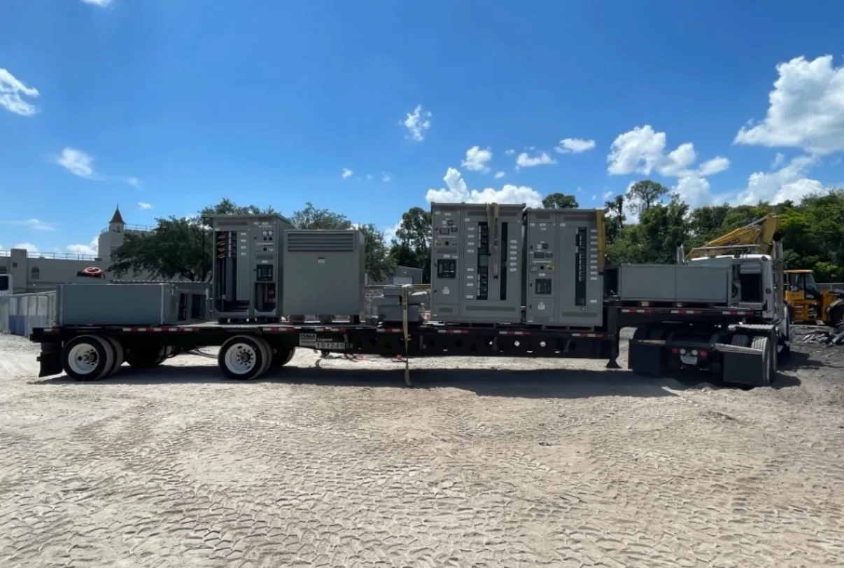
Organizing Motor Control in One Assembly
A motor control center brings motor starters, feeder devices and related controls into a coordinated assembly. For a Nevada manufacturing plant, water facility or other industrial installation, the starting point is a motor list rather than an assumed standard lineup. Identify each motor's supply voltage, running and starting characteristics, control method, operating duty and location, along with any nonmotor loads served from the same equipment.
New equipment can be planned around present production requirements and reasonable provisions for future changes. Space for additional units must be evaluated along with bus capacity, protective devices, ventilation and physical clearances. A qualified electrical engineer should review the connected loads, short-circuit study and applicable code requirements before the construction is finalized.
Starters, Drives and Control Functions
Across-the-line starters, reduced-voltage starting methods and variable frequency drives serve different operating needs. Starter selection should consider motor torque, starting current, supply limitations and the driven equipment. Overload protection must suit the motor and duty, while disconnecting and short-circuit protection are selected as part of the complete branch circuit rather than assumed to be interchangeable with overload protection.
VFD integration adds questions about heat dissipation, drive bypass, communications, cable routing and motor insulation. Long motor leads, harmonics, grounding and electromagnetic interference may require particular attention to the drive and motor manufacturers' instructions. Decide where local controls, status indication and remote signals will be provided, and document how the system behaves after a power loss or protective trip.
Control details deserve attention at the unit level as well as on the overall lineup. The drawings should distinguish local and remote commands, maintained and momentary inputs, indication contacts and any permissives required before a motor can run. For a drive, identify who supplies the speed reference and how a stop command reaches the unit. An automatic restart after a supply interruption can create an equipment or personnel hazard, so the desired behavior should be assessed with the process and safety teams rather than left to a default setting.
Fault Duty and Feeder Coordination
The available fault current at the motor control center depends on the upstream source, transformer, conductors and protective devices. Specify a short-circuit current rating appropriate to that calculated duty and to the assembled combination of components. Individual device markings do not automatically establish the rating of the complete lineup. The proposed assembly and its protective devices need to be reviewed against the project study.
Feeder protection should also be coordinated with branch-circuit devices and upstream equipment. The aim is to limit the effect of a fault while meeting conductor and equipment protection requirements; selective operation must be verified, not assumed. Identify grounding conductors, neutral requirements if applicable, control power sources and any interconnections with plant shutdown systems on the one-line and control drawings.
Enclosures, Environment and Maintenance Access
Dust, heat, washdown exposure and the environment in a Nevada installation influence enclosure selection. Outdoor use or a corrosive process area may require a different construction from a clean indoor electrical room. Specify the expected ambient temperature and ventilation conditions, and review how installed drives and other heat-producing devices affect the assembly. An enclosure designation should be matched to actual exposure and equipment instructions.
Provide the working clearances required by the applicable code and enough practical room to open doors, route cables and service units. Where removable or withdrawable units are proposed, verify the supplied construction and the space needed to handle them. Access does not eliminate electrical hazards: maintenance procedures, isolation, verification of absence of voltage and appropriate protective practices remain essential for qualified personnel.
Defining a U.S.-Manufactured Lineup
A useful equipment inquiry includes the one-line diagram, motor and load schedules, available fault current, enclosure conditions and the desired control architecture. Add preferred starter types, drive features, spare compartments, cable entry and instrumentation requirements. Check whether UL 845 is required for the motor control center, and confirm the applicable standards and construction for each proposed assembly before accepting the submittal.
For equipment manufactured in the United States, identify any domestic sourcing requirements separately from the assembly location. If all-American components are requested, specify the scope and ask for confirmation against the actual bill of materials; do not assume every available device satisfies that requirement. Factory documentation, field wiring responsibilities and commissioning procedures should be agreed with the project team.