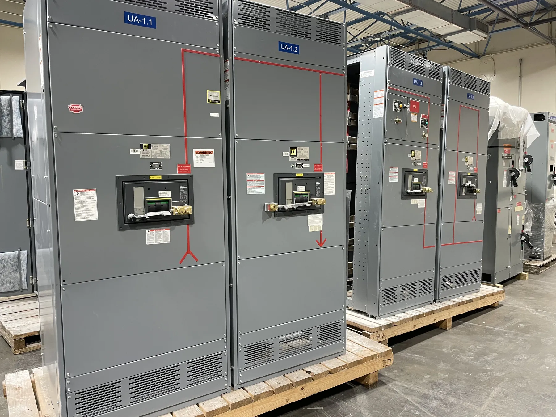
How Custom Switchgear Manufacturing Begins with the Project
Custom switchgear manufacturing starts with understanding what the equipment must connect, control and protect—not with selecting a cabinet from a generic catalog. For a facility project, the manufacturer needs to know the intended system arrangement, the source and outgoing circuits, the installation environment, and the interfaces with transformers, generators, utility equipment, downstream distribution and building controls. Those details shape the lineup, its compartment arrangement, the bus configuration and the space reserved for cable entry and termination.
For Nevada projects, planning also means accounting for the actual installation location. Indoor electrical rooms and outdoor enclosures impose different requirements for access, environmental exposure, heat management and maintenance clearances. Available floor space, door swing, conduit routes, equipment movement into the room and the sequence of construction can all affect a practical design. Shipping nationwide from a U.S. manufacturer supports project coordination, but delivery planning still depends on the site’s receiving access, unloading arrangements and installation schedule.
Engineering the Lineup and Its Interfaces
Engineering translates the project requirements into drawings and equipment details that can be reviewed before fabrication. Depending on the application, the design may address service entrance or distribution functions, main and feeder devices, metering, control power, instrument transformers, protective relays, communication points and provisions for future circuits. The required arrangement should follow the electrical one-line diagram and project specifications rather than assumptions based on a similar installation.
Interfaces deserve close attention. Cable entry direction, conductor landing space, bus connections to adjacent equipment, grounding provisions and control wiring connections can determine whether a lineup fits the room and integrates cleanly with the rest of the system. Coordination with the electrical engineer, installer and other equipment suppliers helps resolve conflicts before metal is cut. Where a design depends on specific protective-device settings, fault-duty information or coordination with upstream and downstream equipment, those decisions require qualified engineering review and site-specific system data.
Ratings, Product Scope and Documentation
Ratings describe particular equipment capabilities and are not interchangeable with the system voltage or a general statement that a lineup is suitable for any application. The project team should identify the required voltage class, continuous current, short-circuit or withstand requirements, enclosure conditions and other specification-driven characteristics. The manufacturer can then evaluate the proposed configuration against the equipment design and applicable documentation. Final ratings must be confirmed for the exact assembly and its intended use.
Low-voltage switchboards may be specified to applicable UL 891 requirements when the product scope and configuration support that basis. UL 891 is not a blanket designation for all switchgear, and it does not by itself establish suitability for medium- or high-voltage equipment, busway or every project condition. Listing claims, standards references and certification details should be checked against the documentation for the actual equipment being quoted and supplied. Requirements for other types of assemblies depend on their product category and project specification.
Component Selection and Configuration Tradeoffs
Component selection affects more than the initial equipment schedule. Main and feeder devices must fit the electrical design, available space and coordination requirements, while metering and controls should provide the functions the owner and operator actually need. Choices may include breaker or switch arrangements, trip and protective functions, instrument transformers, metering provisions, control interfaces and communication capabilities. Compatibility among components matters: device footprints, bus connections, wiring access and accessory requirements can influence the overall layout.
Design tradeoffs should be made against the project’s operating priorities. A compact lineup can conserve room, but it still needs workable cable space, access for service and a configuration that can be installed as intended. A provision for future expansion may require additional physical space or a defined extension interface; it should not be assumed that an existing lineup can be extended without review. Component substitutions also require approval when they affect specified performance, coordination, control functions or documentation.
Fabrication, Assembly and Quality Coordination
Once the engineering basis and approved configuration are established, fabrication turns the design into the structural sections, barriers, mounting provisions and enclosure details for the lineup. Assembly brings together the buswork, switching devices, control and metering components, wiring and identification needed for the specified arrangement. Clear, coordinated drawings help keep the manufactured equipment aligned with the intended connections and reduce avoidable questions during installation.
The manufacturer’s stated use of all-American components and U.S. manufacturing is relevant to projects that specify domestic component sourcing or domestic production. Project teams should still review the equipment submittal and component documentation to confirm that the proposed configuration satisfies the contract’s particular sourcing, technical and documentation requirements. Manufacturing origin alone does not establish an equipment rating, listing, code acceptance or utility approval.
Project-Specific Testing, Quotation Inputs and Delivery
Testing should be defined by the project specification and the equipment being manufactured. The scope may include inspections and applicable checks of the completed assembly, but the test plan and any reports must be confirmed for the specific order. A test result applies to the documented equipment and procedure; it should not be generalized to other configurations or treated as a substitute for engineering review, required approvals or verification of the installed electrical system.
A useful quotation package includes the current one-line diagram, equipment schedule, applicable specifications, required ratings, preferred device and control functions, site and enclosure conditions, cable-entry requirements, dimensional constraints, and the requested documentation or testing scope. It should also identify the delivery destination and any known receiving or installation constraints. Missing or conflicting details can affect configuration, price and schedule, so clarifications are best resolved before the design is released for manufacture. Short lead times may be supported, but the actual schedule depends on engineering completion, component selection, approvals and project requirements. Equipment is manufactured new for customer projects and shipped nationwide, including to Nevada; the final configuration, ratings, documentation and delivery timing require confirmation for each order.