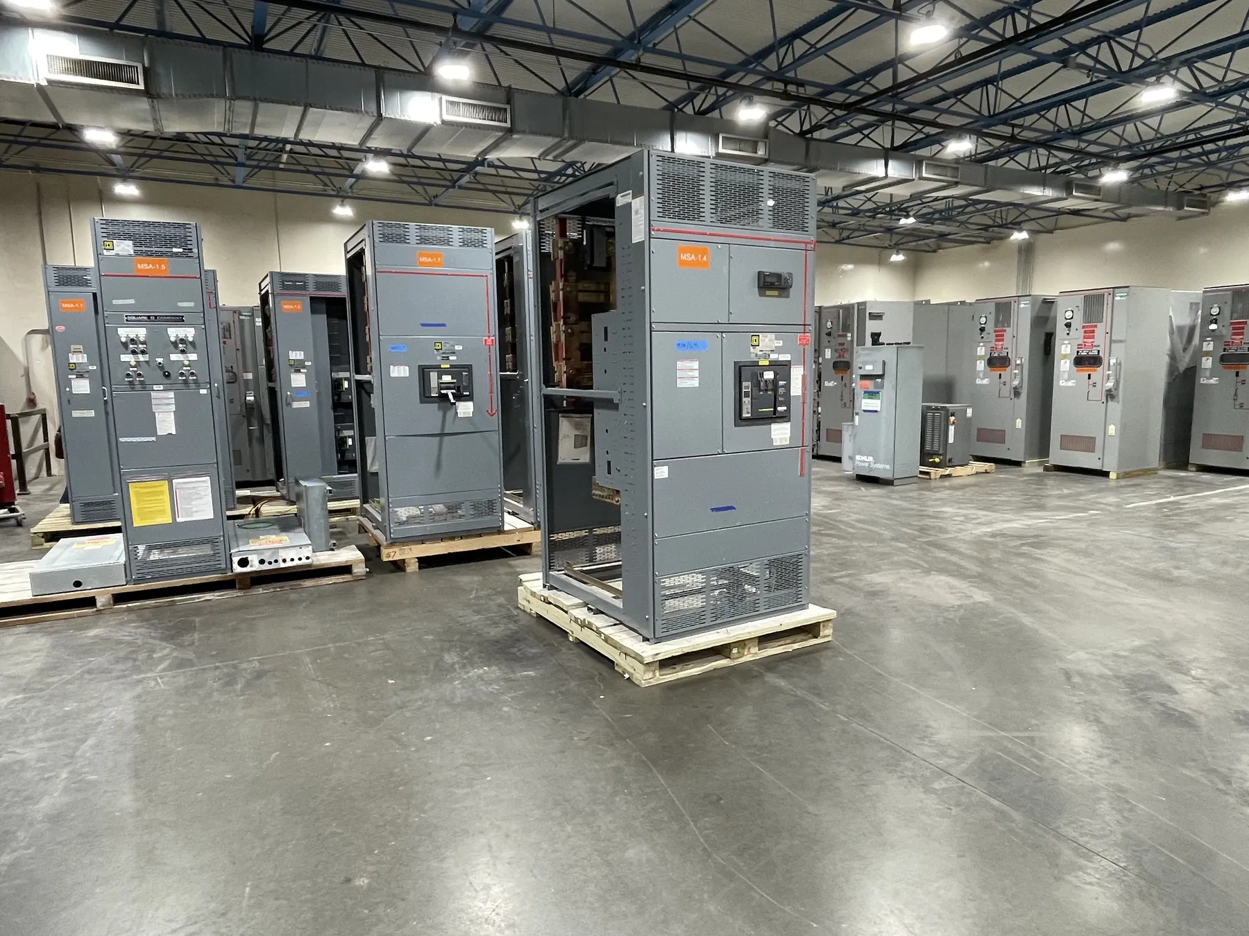
Build the Specification Around the System
A useful equipment specification translates an electrical design into requirements that can be reviewed, manufactured and installed. Start with a current one-line diagram, the location of the equipment and the intended function of each section. For a Nevada project, operating conditions, utility interfaces and the facility's continuity needs may affect the design as much as the physical dimensions of the lineup.
Specify new equipment by its actual product category and voltage class rather than using switchgear as a catchall for every distribution assembly. A qualified electrical engineer should establish applicable codes, perform the necessary studies and resolve interfaces with the serving utility and authority having jurisdiction. The specification is a framework for that work, not a substitute for engineering judgment.
Voltage, Frequency and Continuous Current
State nominal system voltage, phase, frequency and grounding method, along with insulation requirements appropriate to the voltage class. The selected equipment must fit the system and the prospective operating conditions. For medium- or high-voltage equipment, identify project-specific insulation and switching duties and the applicable IEEE or IEC requirements rather than applying low-voltage assumptions.
Continuous bus and device currents should reflect calculated loads, demand, future allowances and the conditions of installation. Ambient temperature, ventilation and enclosure construction can affect equipment selection and any required derating. A large bus rating does not independently establish the capacity of every feeder or protective device. Show individual circuit ratings and equipment connections clearly on the drawings.
Fault Duty and Protective Devices — Switchgear Technical Specifications
Available short-circuit current must be evaluated at the equipment location using the relevant source and distribution data. Specify the required assembly withstand or short-circuit current rating and the interrupting duty of devices in terms appropriate to the equipment. The duration or clearing conditions associated with a rating also matter. Verify the assembled configuration against the calculated duty and the manufacturer's documented application.
Identify breakers, fuses, relays, ground-fault protection and metering where the design requires them. Their characteristics and settings interact with upstream and downstream devices, so coordination should be checked with the actual protective device data. If selective operation or a particular arc-flash risk assessment is required, define the study and documentation scope; neither outcome should be assumed from a component label.
Enclosure, Layout and Site Interfaces
An enclosure specification should describe indoor or outdoor use, temperature, dust, moisture, corrosion and other relevant exposure. Physical design includes cable entry, termination space, mounting, structural support and the clearance needed to operate and maintain the equipment. Outdoor equipment may also require foundation, drainage, security and utility access details. Match any enclosure designation to the actual conditions and construction offered.
Coordinate shipping sections, door swings, conductor routes and field connections with the building and installation plan. Show control power, communications, remote indications and interlocks when needed. Segregation, access features or arc-resistant construction should be identified as specific requirements where applicable, not presumed from a general enclosure description. Qualified installers need the approved drawings and manufacturer's instructions.
Standards, Submittals and Domestic Content
Reference the standards that apply to the particular product and project. For example, UL 891 concerns applicable low-voltage switchboards; it should not be assigned generically to medium- or high-voltage equipment or busway. Panelboards, motor control centers, transfer switches and busway have distinct applicable standards that should be checked against the proposed equipment and local requirements. A cited standard is not by itself evidence of a listing.
For a U.S.-manufactured assembly, provide the one-line, equipment schedule, fault study inputs, environmental criteria and required documentation with the specification. If all-American components are required, define the scope and verify the proposed parts instead of assuming assembly location establishes their origin. Review final drawings, ratings, protective device data and installation responsibilities with the engineer and relevant authorities before release.
Consistency across documents is a valuable final check. A fault duty on the one-line, a device schedule and a written specification should describe the same design basis, including any utility-supplied assumptions. Identify which data remain preliminary and update the affected requirements if transformer size, source impedance or feeder length changes. Submittal review should compare the proposed assembly as a whole with those coordinated documents. Any exception or substitution needs a documented engineering review, because an apparently equivalent component may affect clearances, settings, ratings or the installation sequence elsewhere in the system.