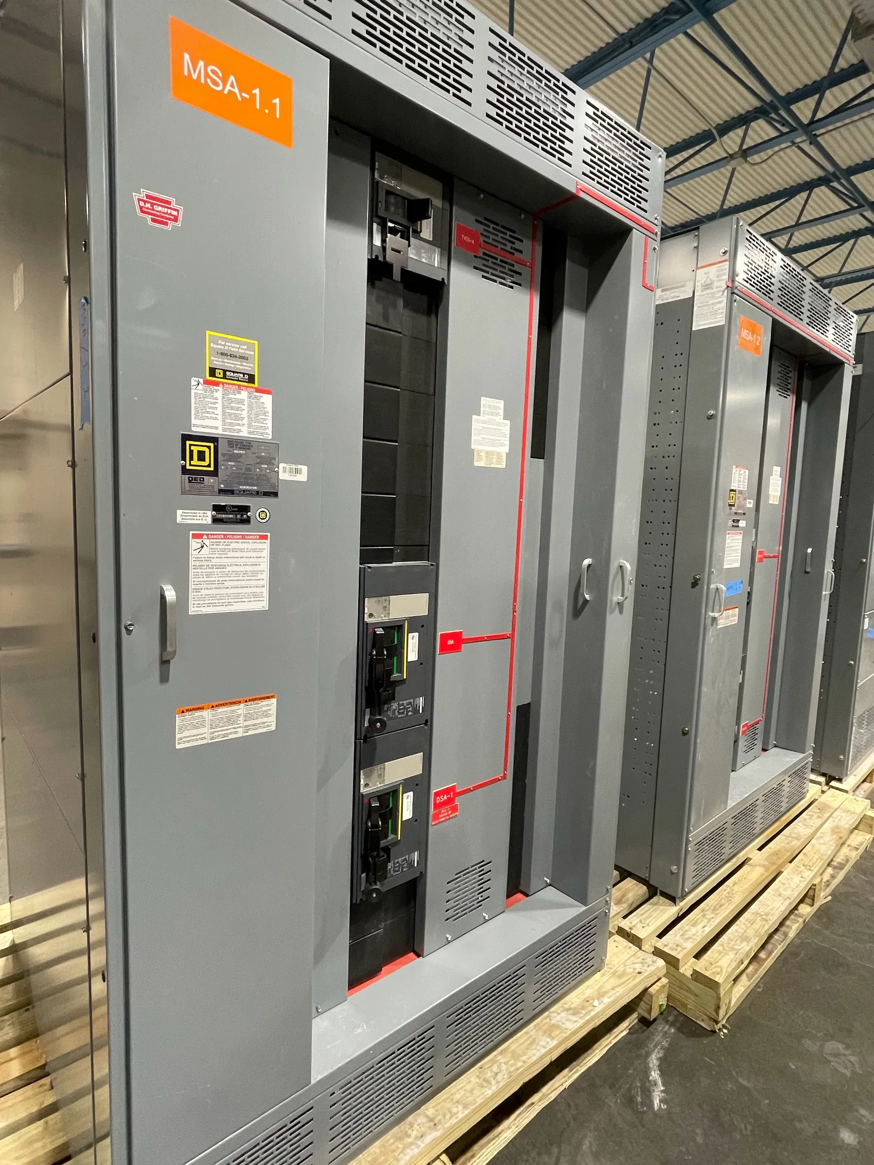
Switchgear Assembly Under an Approved Design
Switchgear assembly turns an engineered electrical design into a coordinated physical lineup. For facility owners, electrical contractors, engineers and procurement teams, the important question is not simply whether components fit inside an enclosure. Bus, protective devices, control wiring, labels and access provisions must correspond to the approved drawings and the intended application. Changes to one element can affect connections, clearances, ratings or the interfaces needed for installation, so design decisions should be resolved through the responsible engineering team before assembly proceeds.
Our manufacturing process is for new custom power-distribution equipment. Assemblies use all-American components and are built in the USA, with nationwide shipping available, including to Nevada. Project timing depends on the approved scope, component selection and production requirements; a specific lead time should be confirmed for the quotation rather than assumed.
Enclosure Layout, Access and Installation Interfaces
The enclosure arrangement establishes the working space for equipment and the connection points for the field. Section dimensions, door and cover locations, barriers, cable entry areas and access to devices must align with the approved layout and the planned installation. For example, a bottom cable entry may affect how feeders approach a section, while a top entry can require a different arrangement of conductors and landing space. These are design coordination items, not details to leave to the final installation stage.
Project teams should identify site constraints that could affect the lineup, such as room access, available footprint, equipment orientation, conduit or cable routing, and restrictions on moving equipment into its final position. Nevada facilities may differ substantially in building layout, ambient conditions and installation logistics; the equipment configuration should be reviewed against the actual site documents. Shipping arrangements and unloading responsibilities also need coordination, without assuming a particular delivery method or site capability.
Bus Selection and Connection Coordination
Bus provides the conductive path between sections and devices, so its arrangement must follow the approved electrical design. The design team establishes the applicable system voltage, current and short-circuit requirements, while the manufacturer applies the specified bus configuration and compatible connection interfaces. A rating is not the same thing as system voltage: each value describes a different part of equipment selection, and both must be checked against the project requirements.
Connections between sections, incoming conductors, feeders and protective devices require particular attention to alignment and available space. The specified conductor approach, lug or termination requirements, phase arrangement and connection orientation should be clear before the build is released. If field conditions prompt a change, it should be reviewed and documented by the appropriate qualified engineering parties rather than treated as a minor fabrication adjustment. Final ratings and product details depend on the approved design and project review.
Protective Devices, Wiring and Labels
Protective devices are selected and positioned to match the intended distribution scheme and the approved device schedule. Frame or trip selections, accessories, control functions and connection details must be coordinated with the one-line diagram, panel or device schedules, and control requirements. Device ratings and settings cannot be chosen responsibly from a general description alone; they depend on engineering analysis and the characteristics of the installation.
Control and auxiliary wiring connects devices and provides the functions specified for the assembly. Wire routing, terminal identification and separation from other conductors should follow the approved drawings and applicable project requirements. Labels likewise need to correspond to the final configuration: equipment identification, source or feeder designations, warning information and device references must be consistent across the assembly and its documentation. Clear, accurate labels help installers and facility personnel identify equipment, but they do not replace site-specific operating procedures or qualified review.
Documented Inspection and Change Control
Assembly should proceed against a controlled set of approved drawings, bills of material and project requirements. A documented inspection plan defines what is checked during manufacturing and what records are retained. Depending on the approved scope, inspections may address enclosure construction, component placement, bus and connection details, wiring against drawings, labels and completeness of the delivered documentation. The plan must be agreed for the particular project; no inspection description should be read as a claim of a specific test result or certification.
When a drawing discrepancy or component substitution arises, the issue should be recorded and routed for authorized disposition. That discipline helps prevent an undocumented change from affecting coordination with upstream or downstream equipment. Any required ratings, listings, tests or acceptance criteria need explicit confirmation for the product and application. UL 891 applies to applicable low-voltage switchboards; it does not automatically apply to every switchgear assembly or to medium- or high-voltage equipment. Listing status and the appropriate standard must be verified for the specific quoted configuration.
Information Needed to Quote a Custom Assembly
A useful quotation begins with enough engineering and installation context to define the equipment rather than a broad label such as “switchgear.” Provide the approved one-line diagram and relevant specifications when available, along with system voltage, required equipment ratings, incoming and outgoing feeder information, device schedules, enclosure and section requirements, control needs, and any specified listing or inspection criteria. Include available room or site drawings, cable entry preferences, shipping destination in Nevada or elsewhere, and the expected project milestones.
These inputs help identify questions that could affect design, component coordination, scope and schedule before manufacturing begins. If details remain open, note them as pending instead of treating an assumption as a confirmed requirement. The final arrangement, ratings and applicable compliance details require review by qualified engineering personnel against the project documents and site conditions. Once the scope is clarified and the design is approved, the manufacturing team can assemble the new equipment to that documented basis and coordinate shipment nationwide.