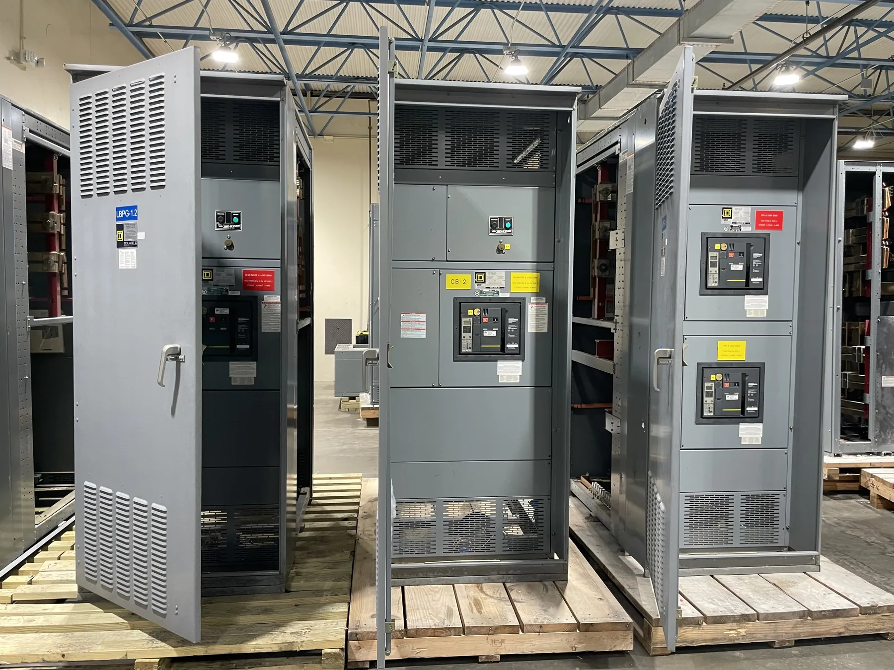
Switchgear Engineering for Distribution Projects
Switchgear engineering turns a facility’s electrical requirements into a defined equipment scope that can be reviewed, manufactured and integrated with the wider distribution system. For owners, electrical contractors, consulting engineers and facility teams, the starting point is not a preferred product label. It is a clear account of what the equipment must connect, what loads it serves, and how it must respond to normal and fault conditions.
Engineering for a custom assembly depends on project documents and verified site information. A one-line diagram, load data, system voltage, available fault-current information and upstream and downstream device details help establish the design basis. When any of those inputs are preliminary or unavailable, the uncertainty should be identified rather than silently replaced with an assumption. That distinction matters to equipment selection, protection review, quotation scope and later submittal approval.
Our U.S.-built equipment uses American components and is designed for projects throughout Nevada and nationwide. Engineering scope is limited to defining and documenting the equipment being manufactured; it does not replace the project engineer’s system design or the electrical contractor’s field installation. Site conditions, interfaces and applicable requirements need review by the qualified professionals responsible for the project.
Load Data, Voltage and Equipment Configuration
Load information helps determine how a distribution assembly should be arranged. Useful inputs include connected loads, expected demand, load type, planned growth, operating schedules and any known requirements for spare or future sections. A total load figure alone may not explain how loads are distributed across feeders, whether particular loads have different operating characteristics, or what switching and metering provisions the project needs.
Confirm the system voltage and configuration separately from equipment current ratings. Voltage describes the electrical system and the equipment’s intended application; an ampere rating describes a current-carrying limit under stated conditions. Neither value can be inferred from the other. The project documents should also establish the number and arrangement of sources, incoming and outgoing connections, and any transfer, tie or sectionalizing functions in scope.
Space and connection choices affect the equipment design. Cable entry direction, termination requirements, conductor routing, access clearances and the location of adjacent gear can influence section arrangement and enclosure details. Nevada facilities may have differing building layouts, environmental conditions and delivery constraints, so project-specific information should be provided rather than assuming a standard room or installation arrangement.
Fault Duty and Protective Coordination
Available fault current at the equipment location is a key design input. It must come from a qualified system study or other project documentation appropriate to the installation; it should not be guessed from the service voltage or a nearby equipment rating. The equipment’s short-circuit withstand or interrupting characteristics, as applicable to the selected configuration, must be evaluated against the system conditions and the role of each device.
Protective coordination is a system-level review of how protective devices are expected to respond to overcurrent conditions. Breaker types, trip functions and settings, fuse selections, transformer characteristics and upstream utility or service-device information can affect the analysis. Coordination goals may compete with other needs, including equipment protection and limiting the effects of faults. The responsible engineer determines the study assumptions and acceptable results; equipment engineering can use approved requirements to document the applicable device and configuration details.
Changing a protective device or setting can affect more than the switchgear section where it is installed. It may alter selective coordination, incident-energy analysis inputs or the performance of downstream circuits. For that reason, project documents should identify the intended devices and make clear who is responsible for coordination studies, setting decisions and final system approval. A manufactured assembly should not be treated as a substitute for those engineering judgments.
One-Line Diagrams and Interface Information
The one-line diagram communicates the system’s topology: sources, buses, protective devices, transformers, feeders and major connections. It is a central reference for translating project intent into an equipment arrangement, but it may not contain every detail needed to manufacture an assembly. Schedules, specifications, cable and termination data, control diagrams and written scope clarifications can fill in important gaps.
Pay particular attention to interfaces between the switchgear and connected equipment. These can include incoming service conductors, transformer secondary connections, generator or alternate-source connections, bus ties, control wiring, metering signals and communications. Identify which items are furnished with the assembly and which belong to other project packages. Clear boundaries help prevent omissions and conflicting assumptions, especially when multiple vendors or contractors are involved.
For custom equipment, quotation inputs should include the current one-line, equipment specifications, load and fault-duty data, required device information, connection details, project schedule expectations and any known room or access constraints. If the documents conflict, note the discrepancy for resolution. A quotation based on incomplete information should state its design assumptions and exclusions so they can be reviewed before the scope is finalized.
Submittal Review and Design Responsibility
Submittals provide an opportunity to compare the proposed equipment with the contract documents before manufacturing proceeds. Reviewers should check the system configuration, device types and ratings, bus and feeder arrangement, connection orientation, control requirements, metering provisions, enclosure details and listed options against the approved design basis. Comments should identify the relevant document or requirement and distinguish required corrections from preferences or informational notes.
Submittal review does not automatically transfer responsibility for system design, code interpretation or field conditions to the manufacturer. The project’s qualified electrical engineer remains responsible for confirming that the overall system design is suitable, including fault-duty and protective-coordination decisions. The installing contractor is responsible for field conditions and installation within its scope. Manufacturer engineering addresses the equipment design and documentation within the agreed scope, using project information supplied and clarified by the responsible parties.
Changes after review can have consequences. A revised feeder, device selection, control function or connection point may require updated drawings and renewed review of related interfaces. Recording approved changes and maintaining a consistent document set supports a more orderly handoff from engineering to manufacturing and then to installation.
Ratings, Standards and Scope Confirmation
Ratings and standards must be evaluated for the specific product and application. UL 891 applies to applicable low-voltage switchboards; it should not be read as covering every form of switchgear or other distribution equipment. A project’s required listing, product category, system conditions and documentation should be confirmed for the proposed assembly. Do not assume that a standard, listing or approval applies to a different voltage class or product type.
Before equipment is released, confirm the approved drawings, ratings, interfaces and project-specific requirements with the parties responsible for design and installation. A thorough engineering handoff gives Nevada projects and nationwide customers a clearer basis for manufacturing while keeping system design, equipment scope and field work properly distinguished.