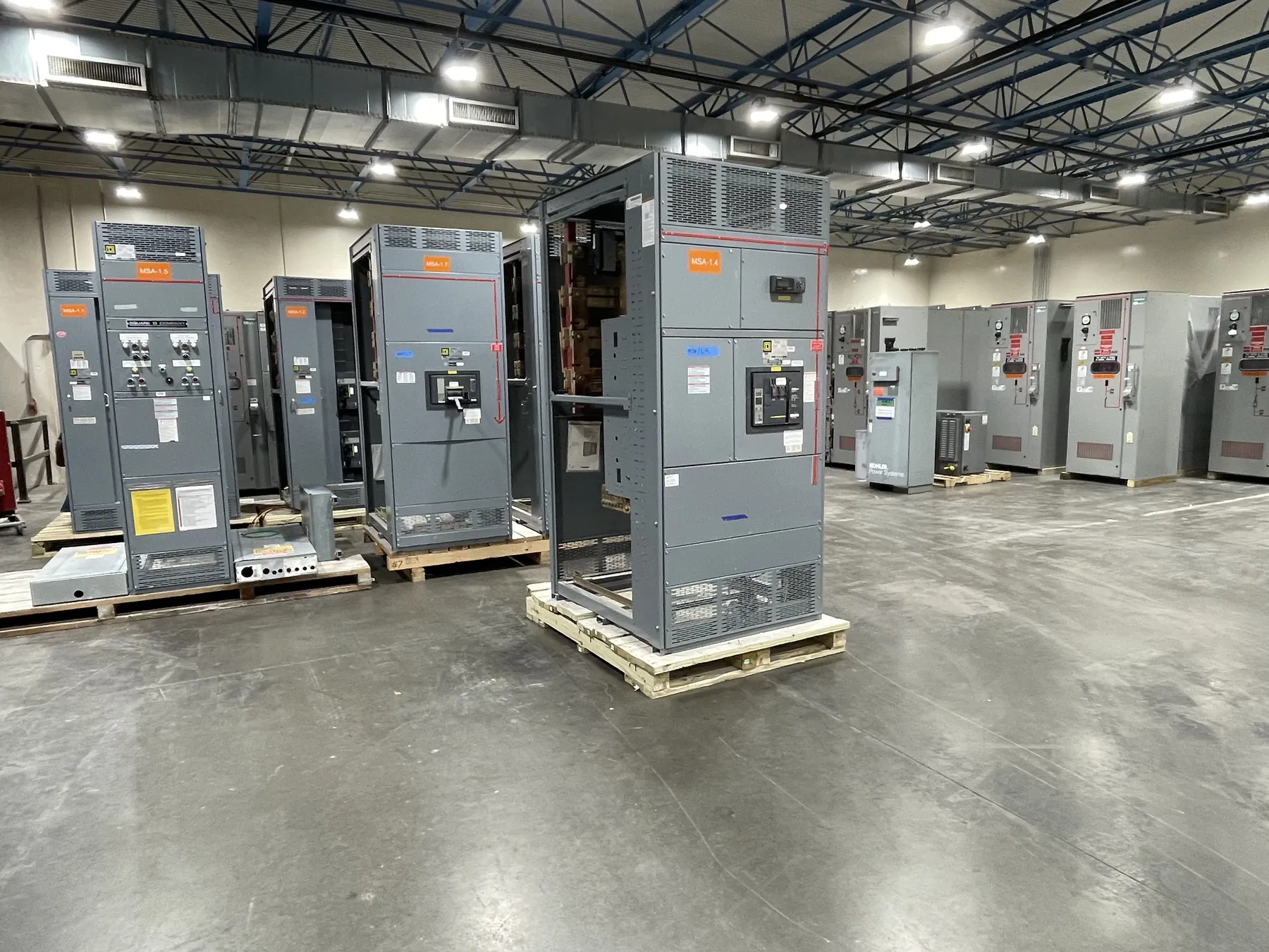
Custom Switchgear Building Starts With the Distribution Plan
Custom switchgear building is the process of configuring electrical distribution equipment around a project’s source, loads, protection strategy, controls and physical installation conditions. The goal is not simply to fit components into an enclosure. The assembly must reflect how power enters the system, where it is distributed, what the connected equipment requires and how the finished lineup will interface with the facility. For Nevada projects, clear early requirements help a U.S. manufacturer develop equipment suited to the specified application and ship it to the jobsite.
A one-line diagram is a useful starting point because it shows the intended electrical relationships: incoming source, main devices, feeder circuits, bus connections and major loads. It also gives the design team a basis for identifying gaps that need resolution. A diagram alone may not capture every physical, control or coordination requirement, so it should be considered alongside project specifications, load information, site constraints and decisions from the responsible electrical engineer.
Define the Source, Main Device and System Interface
Source requirements determine much of the assembly’s configuration. Project documents should identify the intended source arrangement and the electrical characteristics relevant to the equipment, including system voltage, phase, available fault-current information where established, and the expected connection method. A main breaker, main switch or another arrangement may be appropriate depending on the design and applicable project requirements; the equipment manufacturer should not select one without adequate engineering direction.
Source details also affect interfaces beyond the switchgear. Confirm where conductors or bus connections approach the lineup, how the upstream equipment is coordinated, and whether provisions are required for metering, monitoring or control signals. If multiple sources or transfer functions are involved, describe the intended operating logic and the boundaries between the switchgear and other equipment. Those boundaries should be explicit in the drawings and specifications, rather than left to assumptions during fabrication.
Do not treat a device’s ampere or interrupting rating as a statement of system voltage or overall system capability. Ratings, applicable listings and compatibility with the specified system require confirmation for the actual configuration. UL 891 applies to applicable low-voltage switchboards; it should not be represented as covering every switchgear assembly or other equipment category.
Develop Feeder Requirements Around the Loads
Feeder schedules help translate the one-line diagram into a buildable arrangement. For each outgoing circuit, provide the intended load or destination, protective-device type and rating where specified, conductor or termination requirements, and any metering or control needs. Identify spare or future provisions as such. A spare space is not automatically a complete future feeder: the required bus capacity, device provisions, wiring space and enclosure dimensions need to be addressed in the design.
Grouping and arranging feeders can affect access, conductor routing, heat management and the overall lineup footprint. Large or specialized loads may require different protective or monitoring provisions from general distribution circuits. The equipment design should also account for coordination with downstream devices and the facility’s protection scheme. Selectivity, fault-current performance and protection settings depend on the complete system and must be reviewed by qualified electrical professionals using project-specific information.
Specifications should distinguish what the manufacturer is expected to furnish from items supplied or installed by others. Clarify responsibility for field wiring, external control devices, communications connections, upstream protection and any transition sections. Defining these interfaces early reduces ambiguity in the quotation and helps prevent a physically compatible assembly from being misunderstood as a complete system solution.
Choose the Enclosure for the Actual Installation
Enclosure requirements begin with the installation environment and location. The project team should identify whether the equipment is indoors or outdoors, the expected exposure to dust or moisture, available ventilation, ambient conditions and any space or access restrictions. Enclosure type and construction should follow the applicable project specification and environmental conditions; a generic enclosure description is not enough to establish suitability for a particular site.
Provide the available room dimensions, lineup location, required working and maintenance clearances as determined by the project design, and the route for bringing conductors into the equipment. Note door-swing conflicts, nearby piping or structural obstructions, floor and housekeeping-pad details, and whether the lineup must pass through doors, corridors or other constrained paths before reaching its final position. These details can affect section size, orientation, shipping configuration and installation planning.
For Nevada facilities, logistics should be considered alongside the electrical design. Site access, receiving arrangements, unloading capability, staging space and the route from delivery point to the electrical room may influence how equipment is prepared and coordinated for shipment. Conditions vary by facility, so provide verified site information rather than relying on assumptions based on location alone.
Specify Controls, Metering and Bus Requirements
Controls should be described by function, not just by a list of component names. State which devices need to communicate or interlock, what signals are required, and where control power originates. Identify interface points with building systems or other electrical equipment, including any communication protocol specified by the project. Clear control narratives and wiring diagrams help distinguish equipment-furnished functions from external logic and field connections.
Metering requirements may include monitoring at the main, selected feeders or both, depending on the project’s operational needs. Specify the measurements, display or communications expectations, and any required connection points. The design team should confirm instrument and control arrangements against the system configuration; monitoring provisions do not by themselves establish protection, control authority or system compatibility.
Bus requirements should be defined in relation to the equipment ratings, source and load arrangement, conductor entry, and anticipated connections between sections. Confirm whether the design calls for a particular bus material, arrangement or transition interface, and provide the relevant project criteria for engineering review. Bus rating, temperature considerations, fault-duty requirements and connection details cannot be inferred from a general description such as “heavy-duty” or from system voltage alone.
Prepare a Quotation Package That Can Be Engineered
A useful quotation package brings the electrical and physical information together: the current one-line diagram, feeder schedule, applicable specifications, source data, control requirements, enclosure conditions, lineup dimensions and connection details. Include project-specific requirements for drawings, submittal review and coordination. If information is preliminary, label it clearly and identify who will confirm it. This helps separate firm requirements from open design decisions and supports a more meaningful scope review.
Before release, the responsible engineers and project team should review the proposed configuration, ratings, interfaces and installation assumptions. Custom manufacturing supports equipment built around defined project needs, but it does not replace system engineering or site review. Assemblies are manufactured in the USA using all-American components, with short lead times supported and nationwide shipping available. Final scope, applicable ratings, listing status and project details must be confirmed for the specific equipment and application.