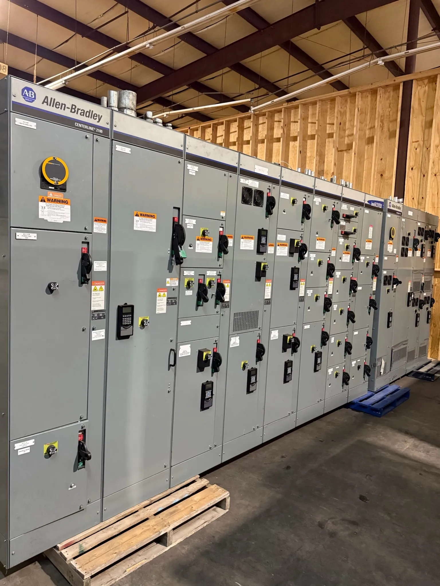
277/480 V Low-Voltage Switchgear: Start with the System
Low-voltage switchgear for a 277/480 V system is selected to fit the electrical service, distribution plan and operating requirements of the facility—not simply because the nominal voltage appears on a project schedule. In a typical four-wire, three-phase arrangement, 480 V is the nominal line-to-line voltage and 277 V is the nominal line-to-neutral voltage. That distinction affects which loads can be supplied from the assembly and how feeders and neutral conductors are specified. Confirm the actual system configuration, grounding arrangement and available voltage from project documents and qualified engineering review before settling the equipment design.
Our U.S.-manufactured equipment is built to order with all-American components and can ship nationwide, including to Nevada. The proposed assembly, component selections and delivery expectations depend on the project requirements and must be confirmed during quotation. The final equipment documentation—not a general product description—establishes the configuration and ratings applicable to the supplied switchgear.
Power Circuit Breaker Arrangements and Serviceability — Low-Voltage Switchgear for 277/480 V
Low-voltage power circuit breaker switchgear can be arranged to serve incoming mains, ties between bus sections and outgoing feeders. The right lineup depends on the one-line diagram, source arrangement, operating priorities and how the facility expects to isolate portions of its distribution system for maintenance. A main-and-tie arrangement, for example, may support a different operating philosophy from a single-main lineup; it does not, by itself, establish that sources can be paralleled or transferred automatically. Those functions require an engineered sequence, compatible controls and confirmation against the actual electrical design.
Maintainability also influences the choice of breaker arrangement and compartment configuration. Consider how breakers are accessed, what equipment must be isolated for inspection or replacement, and whether the facility needs spare breaker provisions or future feeder positions. Physical space, cable entry, working clearances and the location of nearby equipment can constrain otherwise reasonable lineup choices. Review these conditions with the project engineer and equipment manufacturer; a breaker’s drawout or compartment arrangement should not be assumed from the system voltage alone.
Bus Ratings, Fault Duty and Continuous Load
Bus selection is not a one-number decision. The specified bus rating must suit the anticipated load and the lineup’s intended operating conditions, while the assembly’s short-circuit and withstand ratings must be evaluated against the available fault current and protective-device clearing conditions. A higher bus rating does not automatically make an assembly suitable for a particular installation. Source characteristics, transformer data, utility information, downstream equipment and the protection scheme all matter.
When requesting a proposal, identify the desired bus rating if it is established by the design, along with the service and feeder information available. If the project team has not finalized these values, provide the relevant drawings and study inputs so qualified engineers can resolve them. Ratings, construction details and any applicable listing must be confirmed for the specific proposed assembly. UL 891 is a standard associated with applicable low-voltage switchboards; it should not be treated as a blanket standard or listing claim for all switchgear configurations.
277 V Lighting and 480 V Motor Feeders
A 277/480 V distribution system can serve 277 V line-to-neutral lighting loads as well as 480 V line-to-line loads, which may include motors and other three-phase equipment. Each feeder must match the load connection, conductor arrangement and protective-device requirements shown in the approved design. Motor circuits call for attention to starting and operating characteristics, equipment requirements and coordination with the upstream protective device. Lighting feeders require appropriate circuit loading and phase distribution. Neither load type should be assigned solely by nominal voltage without checking the equipment nameplates and design documents.
Neutral sizing deserves specific attention where line-to-neutral loads are present. The required neutral depends on the connected load mix, expected imbalance, applicable code and design assumptions, including the effects of nonlinear loads where relevant. Do not assume that a neutral can be omitted, reduced or sized to a standard percentage for every application. Provide the engineer’s neutral requirements and load information for review as part of the switchgear quotation.
Coordination at the 277/480 V Service
Protective-device coordination is a system-level task. It considers upstream and downstream devices, fault-current conditions, equipment protection and the facility’s desired response to faults. Breaker frame and trip selections, settings, trip-unit features and available fault current all affect the coordination assessment. A device choice that appears appropriate in isolation may not meet the project’s selectivity or protection objectives when evaluated with the complete system.
Supply the latest one-line diagram, available fault-current information, transformer and source details, load data, and any coordination or arc-flash study criteria available to the project team. A qualified electrical engineer must evaluate the design and settings for the specific site. The equipment proposal can reflect documented requirements, but it cannot substitute for engineering analysis or determine code compliance without review of the installation.
Information to Confirm Before Quotation — Low-Voltage Switchgear for 277/480 V
For a useful proposal, provide the nominal 277/480 V system details and service arrangement; incoming and outgoing feeder requirements; expected loads and motor data; neutral needs; bus and fault-duty requirements; breaker functions; cable entry preferences; physical constraints; and any required controls or metering. Include project drawings and applicable specifications when available. Note whether the lineup must accommodate future positions or particular maintenance preferences, since these choices can affect section layout and component selection.
Before approval, compare the proposed lineup drawings and equipment documentation with the project’s electrical design. Confirm the actual system voltage, breaker arrangement, bus ratings, neutral construction, device functions and applicable listing status for the specific assembly. Site conditions in Nevada—including available room, access routes, enclosure location and environmental exposure—may affect layout and installation planning. The final configuration and ratings require confirmation by the responsible engineers and review of the supplied equipment documentation.