Plan a Low-Voltage Switchgear Lineup Around Its Loads
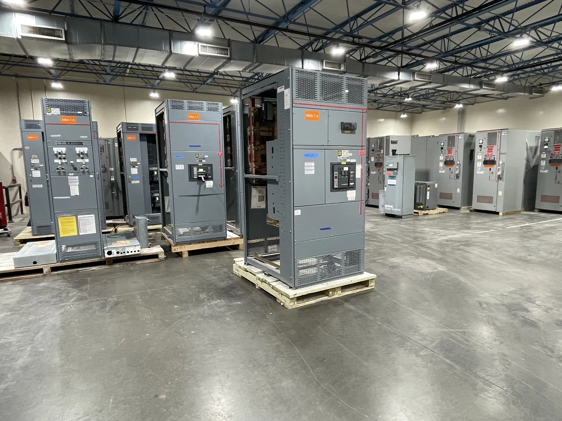
Low-voltage switchgear brings power circuit breakers, buses, controls, and monitoring together in a distribution assembly. For a new Nevada facility or a system expansion, start with the electrical one-line and identify the incoming sources, outgoing feeders, and loads that require continuity. A U.S. manufacturer can use these inputs to develop a new lineup for the project rather than treating every installation as a standard arrangement.
A single-main configuration may suit a straightforward source and feeder system. A main-tie-main arrangement introduces a second main device and a bus tie, but it also requires a clear operating philosophy. State whether transfers are manual or automatic, when sources may be paralleled, and what interlocks are needed. The project engineer must confirm the arrangement against the actual power system.
Compare Power Circuit Breaker Arrangements — Low-Voltage Switchgear
Breaker selection affects isolation, operation, and future maintenance. A drawout power circuit breaker can be moved between designated positions in a compatible compartment; a fixed-mounted arrangement must be assessed differently. Identify which feeders need individual devices and whether remote operation, trip indication, or provisions for a future breaker are required. Available mounting and options depend on the proposed assembly.
Examine the working space in front of each section, the path for moving a breaker, and any lifting or handling equipment specified by the manufacturer. A drawout feature does not make work on energized equipment automatically safe, nor does it eliminate outages for all maintenance. Qualified personnel must follow the facility’s procedures, manufacturer instructions, and applicable electrical safety requirements.
Match Bus Ratings to Operating and Fault Conditions
The main bus must carry the planned load under the equipment’s specified service conditions. Provide calculated demand, expected growth, load diversity, and any unusual operating cycles to the engineering team. Continuous current rating is distinct from the maximum system voltage and from short-circuit withstand capability; none of those values can be inferred from the size of an enclosure.
Compare the available fault current and the required withstand duration with the ratings of the complete assembly. The interrupting capability of each breaker must also be appropriate at its point of application. Ambient temperature, altitude, ventilation, and enclosure selection can affect suitability. Use the manufacturer’s documented ratings and any applicable adjustment guidance rather than assuming a component rating automatically covers the whole lineup.
Coordinate Protection Without Guessing at Settings
Power circuit breakers may offer adjustable protection functions, but useful coordination depends on their actual trip characteristics and the devices upstream and downstream. Provide transformer data, source information, feeder details, and the relevant protective-device curves. An engineer can then evaluate whether a fault on a branch can be cleared by the intended device without unnecessarily interrupting other loads.
Coordination must be balanced against equipment withstand limits and the project’s arc-flash mitigation approach. Delaying an upstream trip for selectivity can change incident-energy exposure, so the tradeoff requires a project-specific study. Ground-fault protection, zone-selective interlocking, and communication functions should be specified only where appropriate and available in the selected configuration.
Specify UL 1558 and Service Access Appropriately
UL 1558 addresses applicable metal-enclosed low-voltage power circuit breaker switchgear. It is different from UL 891, which concerns applicable low-voltage switchboards. When a project specification calls for UL 1558, identify the exact construction and required evaluation. Mentioning a standard does not establish a listing: request documentation for the proposed assembly and its particular options.
Review compartment access, cable terminations, control wiring, and inspection points as part of the submittal. The project’s required front and rear clearances, room dimensions, and delivery path may influence the sectional arrangement. Maintenance access should be evaluated with the actual breaker position and working procedures in mind, not just the footprint shown on a preliminary plan.
Prepare a Nevada Manufacturing Request
Send the U.S. manufacturing team the one-line, intended voltage and bus requirements, fault-duty information, breaker schedule, enclosure environment, and requested standards. Include installation drawings if they show conduit entry, available floor space, and access restrictions. Mark open assumptions clearly so that the proposal can identify decisions still needed before fabrication.
For new equipment manufactured in the United States and shipped to Nevada, specify all-American component sourcing requirements and confirm the origin and availability of the components in the proposed build. Review the final submittal, ratings, and protection design with qualified electrical professionals before release. Delivery planning depends on the approved scope and actual production and transport conditions, not a generic promised date.