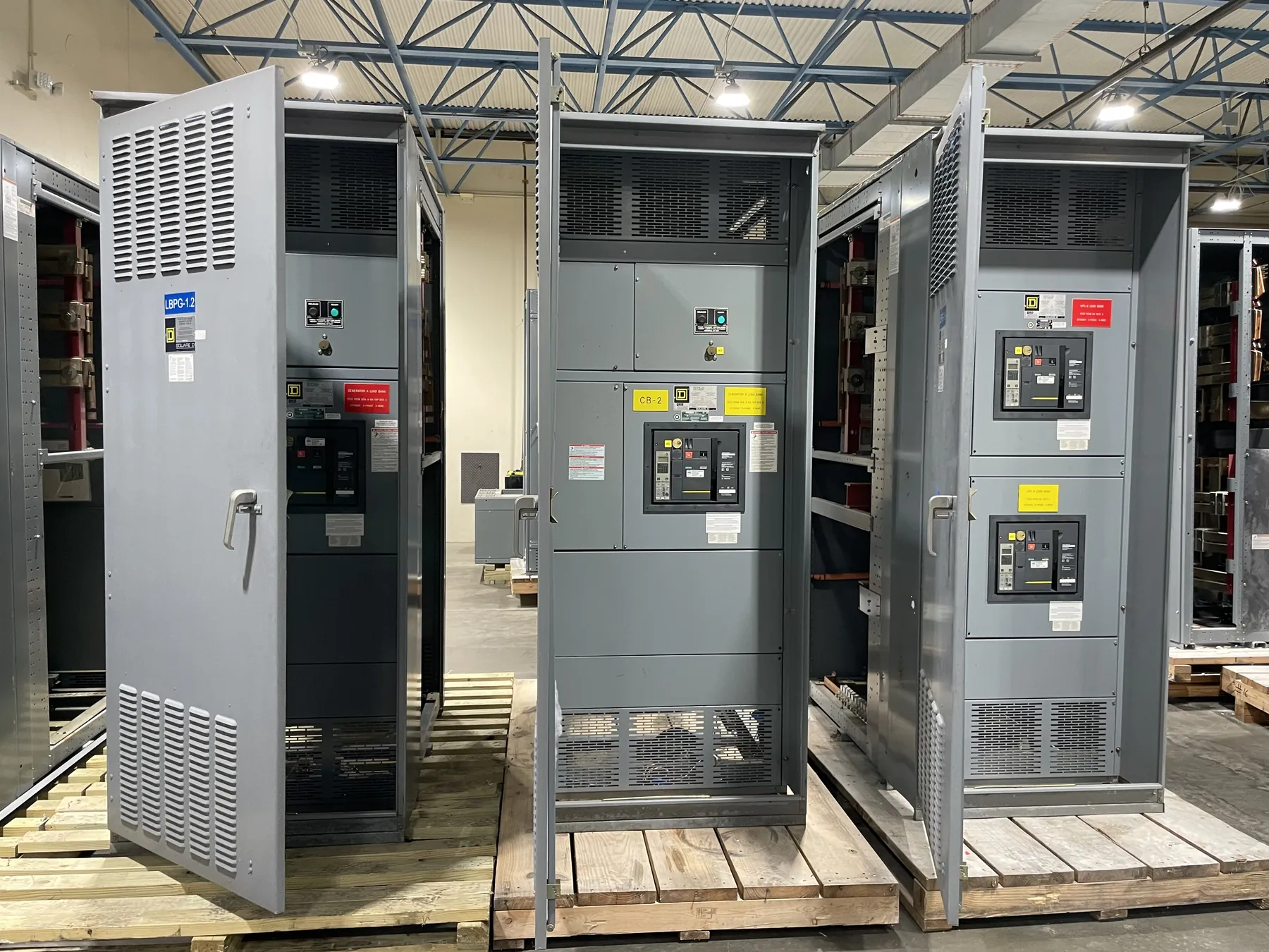
Choose Metal-Enclosed Construction for the Actual Duty
Metal-enclosed switchgear places switching and protective equipment within a metal enclosure, but that description leaves important construction details open. A medium-voltage lineup may use load-interrupter switches with fuses, circuit breakers with protective relays, or another arrangement appropriate to its design. The choice begins with the electrical one-line and the protection, operating, and maintenance needs of the connected circuits.
A U.S. manufacturer serving Nevada can evaluate a request for new metal-enclosed equipment using the project’s source characteristics, voltage class, feeder arrangement, and environmental conditions. Identify the applicable standard and specific construction in the specification. The enclosure label by itself does not establish a short-circuit rating, barrier arrangement, or suitability for a particular installation.
Compare Switch-and-Fuse and Breaker Protection
A load-interrupter switch can be paired with properly selected power fuses in some applications, such as transformer feeders. The switch handles its assigned switching duty, while the fuses provide fault protection within their application limits. Switch load-interrupting capability, fuse interrupting capability, and the ratings of their combination must be checked separately against the actual system.
A circuit breaker arrangement can use protective relays and instrument transformers to detect conditions and command opening. It may be appropriate where adjustable protection or additional functions are required. Compare the need for control power, maintenance, reset procedures, and relay testing with the fuse replacement requirements of a fused design. The qualified engineer must determine which scheme protects the connected load and coordinates with adjacent devices.
Review Barriers Without Assuming Metal-Clad Features
Metal-clad switchgear is a more specifically defined construction within the broader metal-enclosed family. Metal-clad equipment uses compartmentalization with grounded metal barriers and drawout breakers under its applicable standard. A metal-enclosed load-interrupter arrangement may have a different internal layout and should not be assumed to provide the same compartment separation or breaker withdrawal features.
Request drawings showing doors, barriers, shutters where applicable, cable compartments, bus access, and interlocks. Ask which areas may be energized during normal operation and what must be isolated before access. The answers depend on the proposed construction and the site operating procedure. A barrier or interlock assists the intended design but is not a substitute for establishing an electrically safe work condition.
Check Fault Duty and Protection Coordination
Provide the available fault current and the required duration of withstand at the equipment location. The assembly must be suitable for the prospective duty, and each interrupting device must be applied within its documented limits. The switch, fuse, or breaker rating alone does not establish the rating of the complete lineup. Changes in source configuration can change the fault current and should be included in the study.
For fused circuits, examine fuse characteristics against transformer inrush, load requirements, and upstream and downstream protection. Consider the consequences of an operated fuse and possible single-phasing where relevant. For breaker circuits, review relay settings, current transformer selection, and trip power. In either case, the engineer should evaluate ground-fault detection and any gaps in protection using the actual system grounding arrangement.
Resolve Grounding, Cables, and Access
Identify the equipment grounding conductor or grid connection, ground bus details, and bonding between shipping sections. Cable shield grounding and surge protection may require additional coordination with the project design. Grounding provisions must be reviewed together with the system grounding method; neither can be specified reliably from a product name alone.
Show the cable entry direction, conductor size and quantity, terminations, and bending requirements. Include access for inspection and replacement of fuses or service of breakers, along with working clearances and room dimensions. If the lineup is outdoors, describe dust, moisture, temperature, and other exposure so the enclosure and any ventilation can be selected for the intended location.
Specify a New Assembly for Nevada Delivery
A useful manufacturing request includes the one-line, required voltage and current ratings, fault study data, switching arrangement, protection scheme, and installation constraints. Add drawings that show the transformer or feeder interfaces and identify any owner-furnished components. State the applicable IEEE or other standards and request documentation for the particular proposed assembly instead of assuming a certification or test result.
New U.S.-manufactured equipment can be planned for shipment to a Nevada jobsite, with all-American component sourcing identified as a procurement requirement when relevant. Confirm component origins, available options, shipping splits, and the schedule for the actual order. Qualified electrical professionals must review the equipment design and protective coordination before approval, installation, and energization.