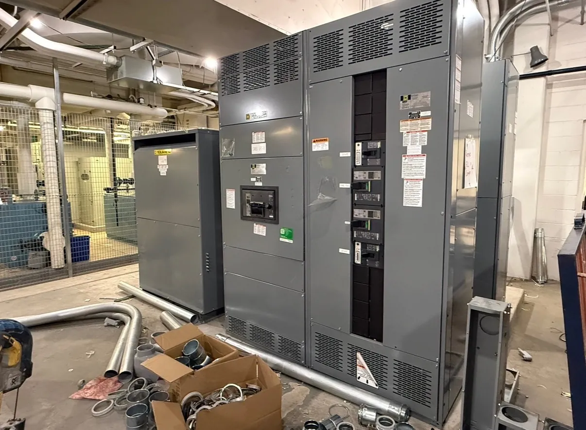
Planning a Pad-Mounted Distribution Installation
Pad-mounted switchgear places switching and protective equipment in an outdoor enclosure, generally at ground level and close to underground distribution cables. A Nevada site may use this arrangement to distribute power among buildings or to connect a facility to a utility system. The actual circuit configuration, voltage class and ownership boundary determine what equipment is appropriate; the name alone does not establish those details.
Begin with the utility and facility one-line diagrams, available fault information and the intended operating practices. Identify normal and alternate feeds, cable terminations, protective devices and future ways that are genuinely needed. A qualified electrical engineer and the serving utility should review the design and interface requirements before the foundation or equipment configuration is committed.
Outdoor Enclosures and Site Conditions
An outdoor enclosure must be selected for the exposure at its actual location. Nevada installations can face intense sun, elevated temperatures, windblown dust and wide temperature changes. Site-specific concerns may also include rain, snow, corrosion, irrigation or vehicle traffic. Communicate the expected conditions and required enclosure features to the manufacturer so that materials, seals, ventilation and finishes can be considered together.
Security and access are separate from weather protection. Identify locking arrangements, working clearances, door swing, operating access and any barriers needed around the pad. Coordinate with the owner on the location of operating handles and warning information. Do not assume that an outdoor enclosure is submersible, arc resistant or suitable for every exposure; those characteristics require explicit verification for the proposed construction.
Foundations, Cable Entry and Grounding
The foundation must fit the equipment dimensions, weight, anchorage pattern and site conditions. Coordinate the pad elevation and drainage with civil design so that water does not accumulate around cable openings or equipment access points. Soil conditions, seismic considerations and local requirements may affect the foundation and anchorage. Final equipment drawings should guide the detailed layout rather than a generic footprint.
Underground duct banks, cable bending space and entry locations need the same early attention as the pad. Confirm cable sizes, quantity, shield treatment where applicable, termination type and any separation between utility and customer compartments. A grounding plan should connect the enclosure and system components as required by the design and local rules. Qualified installers must follow the equipment instructions and utility requirements.
Ratings, Switching and Protection
Specify system voltage and frequency, continuous current, insulation requirements and the short-circuit duties at the equipment location. The required switching capabilities depend on the circuits and operating duties, including whether load switching, fault interruption or isolation is expected. These functions are not interchangeable. Confirm the exact available construction, operating mechanism and device ratings for each way in the lineup.
Protection may involve fuses, relays, interrupters or other devices depending on the equipment and the system design. Coordination with upstream and downstream protection should be based on actual device characteristics and the fault study. Identify applicable IEEE or IEC requirements for the voltage class and project, along with utility standards and authority requirements. The engineer should verify the assembled equipment's suitability, not infer it from a single component.
Utility Interfaces and U.S. Manufacturing
Utility approval can affect the pad location, access route, metering arrangement, compartment layout and permissible operating sequence. Establish who supplies and terminates each cable, who owns the switching devices and how outages will be coordinated. Construction documents should also show spare ducts, control wiring and any remote indication or communications needed by the facility or utility.
When requesting a new U.S.-manufactured assembly, provide the one-line diagram, site conditions, fault duty, preliminary civil layout and utility interface information. If all-American components are specified, define the requirement and verify the proposed component origins instead of assuming domestic assembly establishes origin for every part. Review drawings, installation instructions and acceptance responsibilities with the project team before field work begins.
Operating responsibility should be settled before the compartment layout is approved. Utility personnel may need independent access to their sections, while the facility's qualified operators need clear identification of the ways they are authorized to operate. Describe normal positions, interlocks and key arrangements in the switching plan. If a visible isolation point or a particular means of proving isolation is required, confirm that the proposed devices actually provide it. Switching, testing and grounding procedures must follow the utility's rules and the equipment instructions; enclosure doors alone do not define a safe work condition.