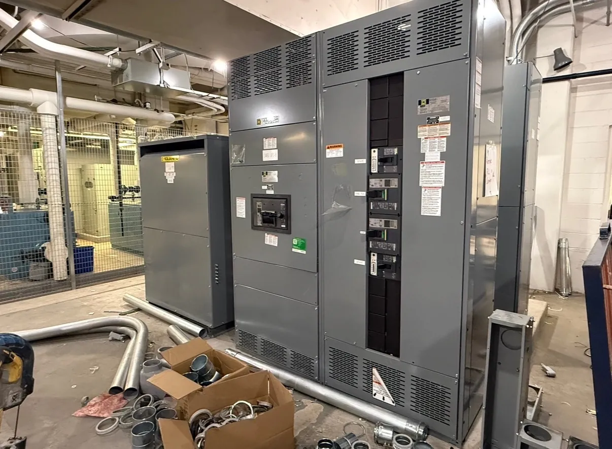
15 kV-Class Pad-Mounted Switchgear: What the Class Means
Pad-mounted switchgear in the 15 kV class is medium-voltage equipment intended for outdoor installation where the project design calls for this voltage class. The class is not, by itself, the complete system voltage or a statement that any particular assembly suits a particular utility or facility. Selection must account for the system’s nominal and maximum operating voltage, grounding method, insulation requirements, fault conditions, switching function and applicable project specifications. Confirm the actual available configuration and ratings in the equipment documentation before treating a product description as a design selection.
This equipment can serve distribution applications that require switching, sectionalizing, protection, or a combination of functions. Those functions depend on the specified arrangement and components; they should not be inferred from the 15 kV class alone. A qualified electrical engineer should review the one-line diagram, system data and operating requirements to establish the design basis.
Outdoor Enclosure, Foundation and Site Conditions
The enclosure and its mounting arrangement must suit the site as well as the electrical design. Project review should address the foundation dimensions and loading, equipment orientation, door and operating clearances, access for installation and future service, and the route by which the assembly will be delivered to its final position. The foundation design and anchorage details should be coordinated with the equipment drawings and site civil design, rather than assumed from a typical pad layout.
Environmental protection is also a configuration issue. Outdoor exposure, precipitation, dust, temperature range, sunlight, corrosion conditions and potential water accumulation can affect enclosure details and material choices. For Nevada projects, conditions differ by location: a facility site may face heat, windblown dust, elevation, or cold-weather exposure, while urban sites may have tighter access and placement constraints. Provide the actual site conditions for engineering review; a general outdoor designation does not establish suitability for every environment.
Cable Entry and Utility or Facility Interfaces
Cable entry needs to be planned around the switchgear layout, foundation and incoming and outgoing circuit routes. Specify whether cables approach from below or another direction supported by the proposed design, along with conductor type and size, quantity, termination requirements, and phase arrangement. Confirm that the entry area, bending space and termination components can accommodate the cables and installation method. These details affect both the equipment arrangement and civil work, so late changes can require drawing revisions.
Utility interface requirements should be identified early. Share the utility’s service characteristics and interface criteria where applicable, including switching and protection expectations, metering provisions, grounding requirements, and any required equipment documentation or review process. Utility acceptance is project-specific and should not be assumed from a voltage-class designation. For privately owned distribution, identify the facility’s operating boundaries, incoming source information and downstream loads so the proposed arrangement can be reviewed against the complete system.
Ratings, Insulation Level and Short-Circuit Duty
Voltage class, continuous-current rating, insulation level and short-circuit duty are related design inputs, but they are not interchangeable. The 15 kV class identifies a broad equipment class; it does not establish the system voltage, the required withstand level, or the fault-current capability of a particular configuration. The engineer of record should determine the required values from system studies, source data and the project’s governing criteria, then verify that the selected equipment documentation matches them.
Short-circuit duty must be evaluated for the actual point of installation and the selected switching devices and assembly. Available fault current, protection clearing time and system configuration can influence the required equipment capability and coordination. Do not select a rating from a general catalog description alone. Ratings and any applicable listing or standard claims must be confirmed for the specific equipment and arrangement. UL 891 applies to applicable low-voltage switchboards; it should not be treated as a standard covering medium-voltage pad-mounted switchgear.
Protective Relaying and System Coordination
Protection choices should follow the project’s protection study and operating objectives. The design team may need to consider relay functions, sensing inputs, trip or control interfaces, source and load characteristics, and coordination with upstream and downstream protective devices. A relay package cannot be specified responsibly without knowing the system grounding, available fault current, equipment arrangement and intended response to different fault conditions.
Provide the one-line diagram, relevant study information, protection philosophy and interface requirements with the inquiry. The manufacturer can use these inputs to evaluate the requested configuration and identify information still needed for a proposal. Final settings, device selection and coordination remain engineering decisions requiring qualified review and site-specific data.
Quotation Details, Documentation and Maintenance Access
For a useful quotation, include the required voltage class, system voltage and frequency, one-line diagram, requested switching and protection functions, continuous-current and short-circuit requirements, cable-entry plan, environmental conditions, foundation constraints, utility criteria and desired documentation. Identify project-specific requirements for controls, metering, labeling, spare provisions or interfaces where applicable. The proposed equipment configuration, ratings and scope should be checked against the final project documents before release for manufacture.
Maintenance access belongs in the layout discussion, not just the operating plan. Show the space available around doors and service points, the approach path for qualified personnel, and any nearby walls, fencing, traffic routes or other equipment that could limit access. The actual maintenance requirements depend on the installed configuration and its documentation. Review them with qualified electrical personnel and follow the manufacturer’s instructions and site safety program. Custom new switchgear is manufactured in the United States using all-American components, with nationwide shipping and support for short lead times; schedule and configuration are confirmed for each project.