Low-Voltage Switchgear with Drawout Breakers: Arrangement Choices
Low-voltage switchgear with drawout power circuit breakers is specified around the electrical system it must serve, not simply the breaker frame. The assembly may include incoming, tie and feeder sections, with breakers selected for each circuit’s duty and operating role. A drawout arrangement lets a breaker move among defined positions in its compartment, but the design still depends on the switchgear structure, bus system, control wiring and project requirements. For a Nevada facility, the specification should reflect the actual one-line diagram, utility and transformer interfaces, environmental conditions, and the owner’s maintenance approach.
Key decisions include the number and location of breaker sections, whether a bus tie is required, how loads are divided, and which circuits need individual power circuit breakers. A main-tie-main arrangement, for example, has different operating and coordination considerations from a single-ended lineup. The engineer should establish the intended normal configuration and any permitted alternate configurations before equipment is finalized.
Connected, Test and Disconnected Positions — Low-Voltage Switchgear with Drawout Breakers
In the connected position, the breaker is engaged with the assembly’s primary disconnects and is in its intended circuit position. In the test position, primary power connections are separated while designated secondary control circuits can remain connected for applicable functional checks. In the disconnected position, both primary and secondary connections are separated according to the equipment design. These terms describe equipment positions; they do not replace the manufacturer’s instructions or site-specific operating and safety requirements.
Position indications, mechanical interlocks and any key or electrical interlocking scheme should be reviewed against the operating sequence. Interlocks may prevent certain movements or actions, but their presence and scope vary by design. Confirm the documented functions, control-power requirements and interface with protective relays or supervisory controls. Do not infer a particular interlock feature from the word “drawout”; it must be specified and verified for the proposed assembly.
Breaker Interchangeability and Maintainability
Interchangeability can help a maintenance plan, but breakers should not be assumed interchangeable merely because they share a nominal frame size or appear similar. Compatibility may depend on the switchgear model, compartment construction, primary disconnects, secondary contacts, trip unit, control voltage and other configuration details. Where spare breakers or future circuit changes matter, identify the exact intended interchangeability in the equipment requirements and request supporting documentation.
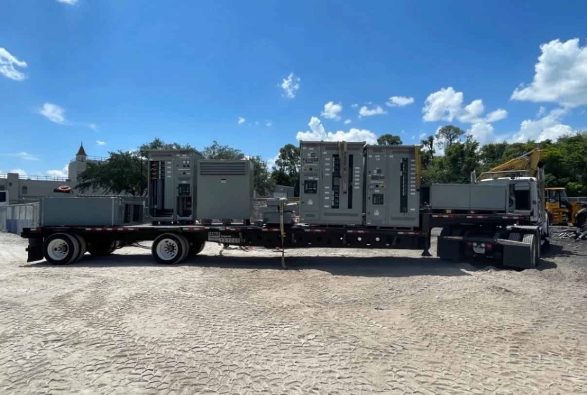
Maintainability also depends on access, lifting and handling provisions, available space in front of and around the lineup, and how control and communication connections are arranged. Room layout should account for the actual equipment dimensions and the facility’s access constraints. In Nevada, shipping and site logistics should be coordinated with receiving access, unloading capability, route restrictions and the installation schedule; those details can affect how a lineup is divided and delivered. Qualified personnel must plan work in accordance with the equipment instructions and applicable site procedures.
Bus Ratings, Breaker Ratings and Fault Duty
Bus continuous-current ratings, breaker ratings and system voltage describe different aspects of the design and must be checked separately. The specified bus rating should suit expected loading and the system design, while the breaker’s interrupting and withstand capabilities must be appropriate for the available fault conditions at its location. Do not treat a breaker rating as the rating of the complete switchgear assembly. The actual assembly’s short-circuit or fault ratings, including any conditions or limitations, must be confirmed from its documentation.
System voltage is not interchangeable with a voltage rating, and a rating alone does not establish suitability for a specific installation. The engineer should review the one-line diagram, grounding arrangement, source characteristics, transformer data and calculated available fault current. Bus configuration, temperature and environmental conditions, enclosure selection, and future load assumptions can also affect equipment selection. Final ratings and application suitability require engineering review and confirmation for the project.
Coordination and Protection Interfaces
Breaker and trip-unit selection should be coordinated with upstream and downstream protective devices using the project’s protection objectives and system study. Selectivity, clearing times, equipment withstand limits and arc-flash analysis can influence settings and device choices. A drawout breaker does not by itself ensure selective coordination or reduce incident energy. Protection settings and performance depend on the complete system, the chosen devices and the engineer’s analysis.
Document the control scheme, trip and close circuits, auxiliary contacts, relay functions, metering and communications required at each breaker. Confirm the intended interface to facility controls and any external protection devices. Changes to a feeder or source arrangement can alter fault levels and coordination, so the final design should be checked against the actual installation rather than relying on a generic lineup description.
Standards, Documentation and Quotation Inputs
UL 1558 may be relevant to low-voltage metal-enclosed switchgear when it applies to the proposed equipment and project requirements. It should not be assumed to cover every low-voltage product or to establish that a particular assembly is listed. Applicable standards, listing status and project-specific compliance must be confirmed for the offered configuration and documented equipment. Ratings, construction details and available options likewise require confirmation; no particular configuration should be presumed available without review.
For a useful quotation, provide the one-line diagram, system voltage, bus and breaker rating requirements, available fault-current information, source and tie operating scheme, feeder schedule, control voltage, protection and communications needs, and installation conditions. Identify required positions, interlocks, spare or interchangeable breakers, enclosure details and applicable project specifications. U.S.-manufactured assemblies use all-American components, support short lead times and ship nationwide, including to Nevada. The actual configuration, ratings, listing status, schedule and shipping plan are confirmed against the project documents and equipment requirements.