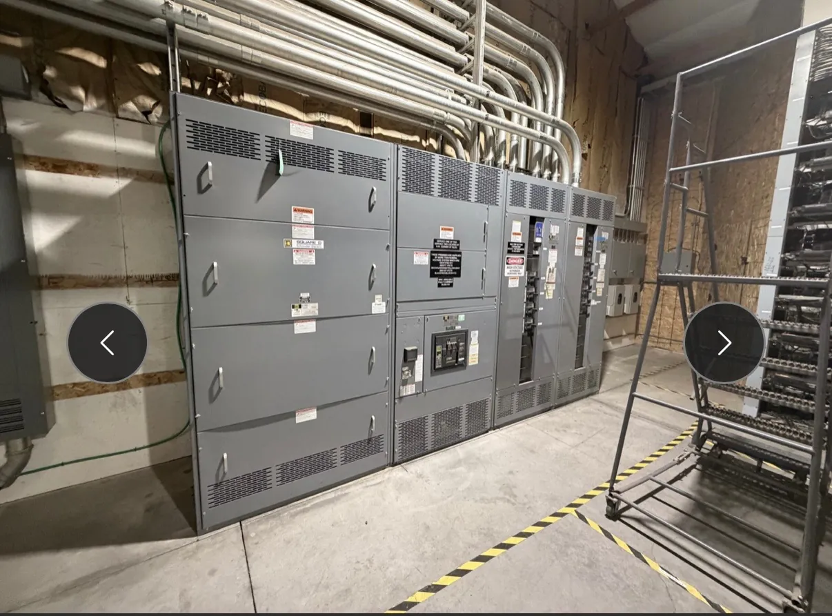
Planning Service Entrance Switchboards for Yerington Projects
A service entrance switchboard establishes the point where a facility’s electrical service is received, metered as required, and distributed through its main disconnect and downstream feeders. For a Yerington project, the design begins with the serving utility’s service requirements and the building’s electrical plans—not with a presumed standard arrangement. Site conditions, planned loads, metering rules, available fault current and the authority having jurisdiction all affect the section layout and equipment selection.
Our U.S.-built equipment is custom manufactured with all-American components and can be shipped to Nevada. To develop a useful quotation, provide current one-line diagrams, service and load information, project specifications, utility criteria and the intended installation space. Those inputs help identify design questions early; final ratings and construction details require review by qualified electrical professionals and confirmation against project documents and applicable requirements.
Coordinate Utility Metering and the Service Interface — Service Entrance Switchboards in Yerington, NV
Metering arrangements are determined by the serving utility and project conditions. Before the switchboard is configured, establish whether metering is utility-furnished or part of the equipment scope, where the meter section must sit, and what access, compartment separation, provisions or clearances are required. Confirm the utility’s current service manual and any project-specific direction rather than assuming a meter socket, instrument-transformer compartment or other configuration will be accepted.
The service interface also affects bus arrangement, conductor entry, section sequence and physical dimensions. Utility service conductors may enter from the top or bottom, depending on the site and approved design. Record the intended entry direction, conductor information when available, routing constraints and location of the service point. Any unresolved utility requirement should remain an open coordination item until the responsible parties confirm it.
Define the Main Disconnect and Protection Needs
The main disconnect must fit the service arrangement and the protection strategy established by the project engineer. Relevant inputs include service characteristics, calculated load, expected operating conditions and the protective devices coordinated downstream. A switchboard’s voltage and current ratings are distinct from the actual system voltage and load; neither should be inferred from a building type or location. Interrupting and withstand capabilities must also be evaluated against available fault current at the equipment location.
Provide the latest available fault-current information and identify who will verify it. If utility data or upstream equipment details are pending, note that status in the quotation package. A change in source transformer, conductor length or upstream protective device can affect the study and equipment selection. Final fault-current adequacy and protection coordination require project-specific engineering review, not a generic assumption.
Resolve Grounding, Bonding and Authority Requirements
Service grounding and bonding details depend on the system configuration and applicable project requirements. The design team should identify the grounding electrode system, bonding points, neutral treatment and any separation required between service and downstream equipment. These details influence the service section and its connections, so provide the electrical drawings and specifications that establish the intended arrangement.
Approval responsibilities should be clear before release for manufacture. Confirm the serving utility’s acceptance requirements and identify the authority having jurisdiction for the installation. Utility acceptance, equipment listing, and code compliance are separate matters; one does not establish the others. UL 891 applies to applicable low-voltage switchboards, but it is not a blanket qualification for every product or system. Any applicable listing and the exact equipment scope must be confirmed for the proposed design.
Allow for Load Growth, Spare Circuits and Future Space
Yerington facilities may have different operating schedules and expansion plans, so document the project’s actual expectations instead of selecting spare capacity by habit. Identify planned load growth, known future additions, the number and type of spare circuits desired, and whether future extensions should be accommodated within the switchboard lineup. Also distinguish an installed spare device from an unused space or a provision for a later section; these are not interchangeable design choices.
Future capacity has physical consequences. Additional sections require room, access and a feasible path for future conductors, while spare devices affect present cost, lineup dimensions and coordination. Share available electrical-room dimensions, access restrictions, wall and floor conditions, conductor routing, ventilation considerations and any known delivery-route constraints. These site details help shape a practical configuration without assuming conditions at an unvisited facility.
Prepare a Clear Quotation and Coordination Package
A complete request should include the one-line diagram, load schedule, utility metering criteria, available fault-current data, grounding requirements, specifications, preferred conductor entry and installation-space information. Add the planned growth, spare-circuit expectations, future-extension intent and required approval contacts. Identify which documents are preliminary and which have been reviewed, so unresolved items can be tracked before equipment details are finalized.
Our manufacturing workflow is based on new custom equipment, with assemblies built in the USA using all-American components. Short lead times are supported, and equipment ships nationwide; an exact schedule depends on the approved design, scope and project coordination. Ratings, listings, dimensions, interfaces and approval details should be confirmed against the final documents before release. This disciplined review helps the service entrance switchboard align with Yerington project requirements while avoiding assumptions about the utility, site or electrical system.