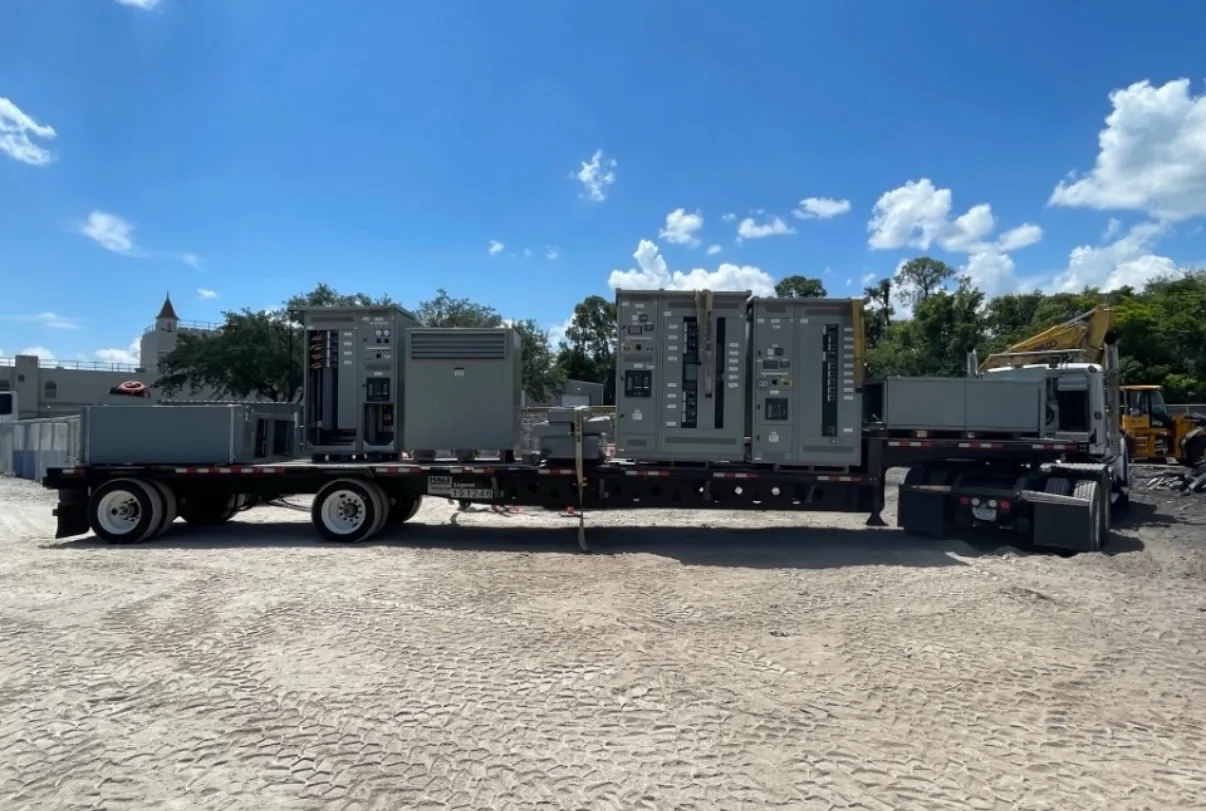
Planning switchgear for a Yerington, Nevada project
For a project in Yerington, the first step is to define what the distribution equipment must serve now and how the electrical system may change. A new switchboard or switchgear assembly should reflect the actual one-line diagram, source arrangement, loads, fault-current information and installation conditions—not just a desired ampere rating. Our U.S.-built, custom distribution equipment is manufactured for customer projects and can ship to Nevada; we do not represent that we have a facility in Yerington or that a particular project is already underway.
At the planning stage, gather the latest electrical drawings and identify the project’s responsible electrical engineer. That engineer can establish design criteria, confirm applicable codes and determine which equipment type and ratings suit the site. A preliminary equipment description is useful for budgeting, but it is not a substitute for reviewed drawings and coordinated project requirements.
Document load growth, spare circuits and extension space
Describe the expected load at initial occupancy as well as planned additions. Identify major loads, anticipated changes in operating schedules and any known future phases. Separating firm requirements from possible expansion helps avoid treating an uncertain forecast as a final design input. The engineer should also determine how demand, diversity and load characteristics affect equipment selection.
Record spare capacity in more than one way. Note the requested spare circuit positions, the kinds of loads they may serve, and whether future loads could require larger conductors or protective devices. A spare circuit position does not by itself guarantee that the source, bus, enclosure or upstream system has capacity for added load. Ask the design team to document those limits and assumptions.
Measure available equipment-room space and the planned route for future extensions. Note wall clearances, door openings, obstructions, ceiling height, cable-trench or conduit entry locations, and the direction in which sections may need to be added. Preserving extension space can compete with room layout, cable access and initial equipment cost; resolve those tradeoffs on the drawings rather than assuming a future section will fit.
Define the electrical ratings and system interfaces
Provide the system voltage, phase and wire arrangement, frequency, source configuration, grounding method and available fault-current information when known. Distinguish system voltage from equipment ratings: a rating is not, by itself, proof that an assembly is suitable for a particular system. The qualified engineer and manufacturer must review the application, protective-device details and relevant ratings together.
Clarify how the equipment connects to transformers, generators, utility service, downstream panels or other sources. Identify incoming and outgoing feeder requirements, cable or bus connections, metering needs, control power, communications and any interlocking or transfer functions. Confirm ownership boundaries and interface responsibilities with the project team and serving utility where applicable; utility requirements and approvals depend on the project and cannot be assumed from a location alone.
For low-voltage switchboards, UL 891 may be relevant to the specified product. It does not apply to every type of switchgear or to medium- and high-voltage equipment, busway, or every assembly configuration. State the required product type and listing expectations in the inquiry so applicability can be reviewed. Do not treat a requested standard, system voltage or component rating as confirmation that a specific assembly is listed or approved.
Account for Yerington site and installation conditions
Yerington’s location makes delivery planning part of the project conversation, but site access varies. Provide the delivery address or project location, receiving contact, access restrictions, unloading arrangements and any required delivery appointments when available. Confirm who will receive the equipment and whether the route from the drop point to the electrical room includes gates, narrow access, stairs or other constraints. These details help the project team assess shipment and handling requirements without assuming a particular site condition.
Describe the intended indoor or outdoor installation, enclosure environment, ambient conditions and exposure to dust, moisture or corrosive influences. Include equipment-room dimensions, floor and anchorage information, cable-entry orientation, ventilation constraints and any restrictions on lifting or section movement. Site conditions can affect enclosure selection, arrangement and installation planning, so they should be reviewed by qualified project personnel.
Prepare a useful quotation package — Switchgear for Yerington, NV
A clear inquiry helps us scope custom-manufactured equipment. Include the one-line diagram, load schedule, equipment schedule, preliminary layout, requested product type, system data, feeder details, control requirements and anticipated expansion plan. Mark items that remain undecided, and identify the engineer or contractor responsible for resolving them. If drawings are preliminary, label them accordingly and note the date or revision.
Also share the project schedule milestones that matter for submittals, design review, release for manufacture and site receipt. Lead time depends on the final scope, approved information and project requirements; no exact schedule should be assumed before those details are reviewed. U.S.-built assemblies use all-American components and can ship nationwide, including to Nevada. Confirm the shipment scope, delivery coordination and any site-specific handling needs during quotation.
Coordinate review before release
Before manufacturing release, the project’s qualified electrical professionals should review the final drawings, ratings, protective-device coordination, interfaces, physical arrangement and applicable code requirements. Confirm that spare circuits and future extension provisions are shown clearly, and that the planned installation space matches the equipment arrangement. Changes to loads, sources or room conditions can affect the design and should be communicated promptly.
For Yerington projects, a complete, carefully reviewed specification supports a practical path from engineering coordination to shipment and installation. The key is to make present requirements explicit, record credible growth plans, and verify every rating, listing and site interface against the actual project documents.