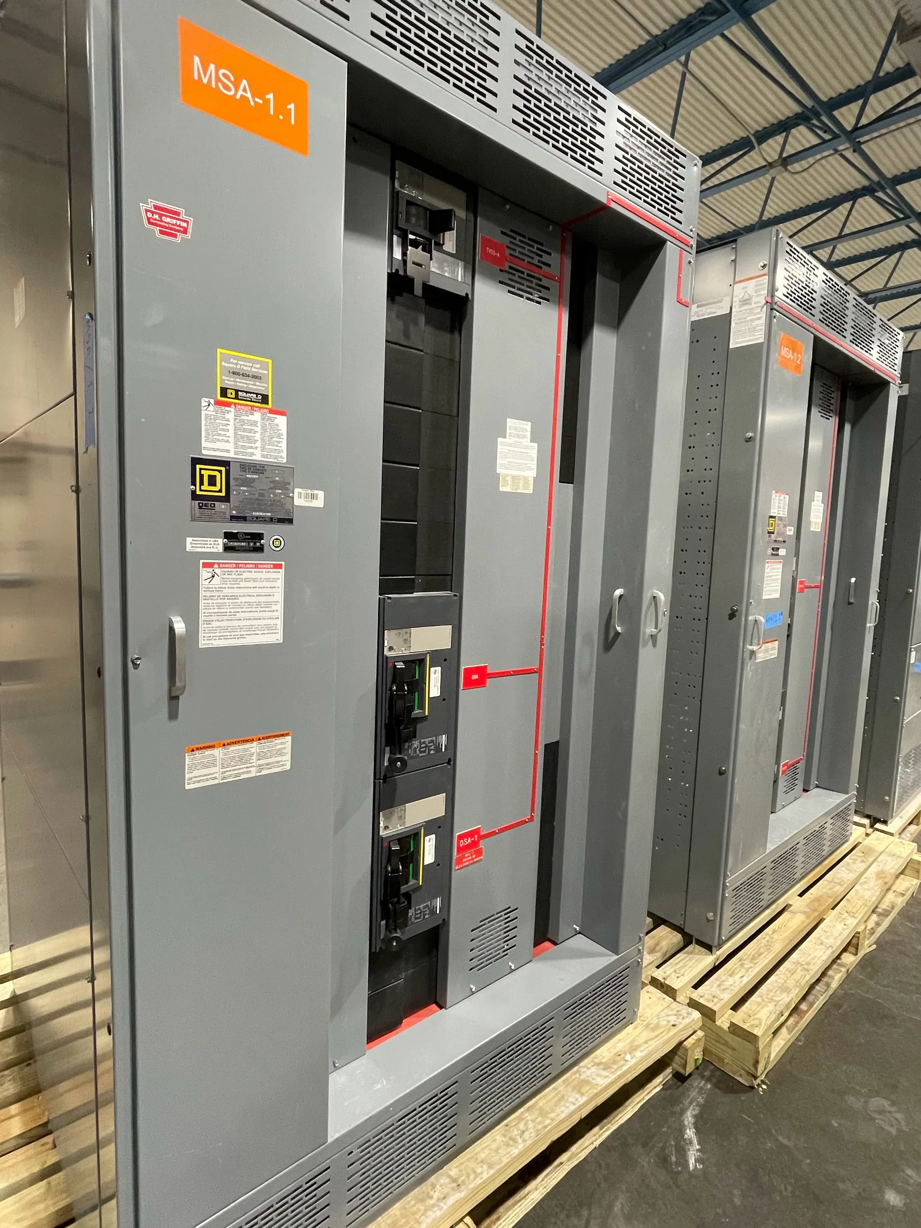
Medium-Voltage Switchgear for Yerington Project Planning
Medium-voltage switchgear is selected around the electrical system it must serve, not simply a building’s location or a nominal voltage label. For a Yerington project, begin by documenting the source and planned system voltage, the equipment’s voltage class, the required continuous current, and the available fault duty at the proposed connection point. These are related but distinct values: voltage class describes the equipment’s design range, while fault duty concerns the short-circuit stress it may need to withstand or interrupt. A qualified engineer should confirm the applicable values using the project’s utility information, system studies, and site conditions.
Load growth deserves attention at the same time as the initial load. Record expected phases of expansion, likely new motors or process loads, and the number and type of spare circuits that may be needed. A lineup sized only for today’s loads can constrain later work; a larger lineup, however, also requires space, access, and a plan for future connections. These tradeoffs should be resolved before equipment layout and quotation rather than left as assumptions.
Voltage Class, Fault Duty, and Insulation Level
The project specification should identify the system voltage and the medium-voltage equipment class separately. The class must suit the system and the applicable design requirements; it should not be inferred from a general description such as “medium voltage.” The available fault current at the switchgear location is another essential input. Source changes, transformer data, conductor impedance, and future system additions can affect that value, so the engineer should establish the design basis and specify the required withstand and interrupting capabilities for the proposed arrangement.
Insulation level is a separate selection that must align with the equipment class, system conditions, and applicable engineering criteria. It is not a substitute for fault-duty ratings. Environmental conditions may also influence insulation and enclosure choices. For a Yerington site, the project team should document the actual installation environment—including indoor or outdoor placement, elevation where relevant to the design, dust exposure, temperature range, and available building protection—rather than relying on assumptions based on the city name.
Ratings are not interchangeable across equipment types, and a system voltage alone does not establish that a particular lineup is suitable. Final ratings, construction, and any applicable listing or standard must be confirmed for the specific design. UL 891 applies to applicable low-voltage switchboards; it should not be represented as a standard or listing for medium-voltage switchgear.
Protective Relays and System Coordination — Medium-Voltage Switchgear in Yerington, NV
Relay functions should follow the protection study and the role of each incoming, tie, or feeder circuit. The engineer must define the protective elements, sensing inputs, trip interfaces, control power, and communications requirements, if any. Settings cannot be selected responsibly from equipment descriptions alone: they depend on source characteristics, connected equipment, grounding method, downstream devices, and the desired coordination with upstream protection.
Coordination should be reviewed across the complete electrical system, including utility or source protection where applicable, transformers, downstream switchgear or motor-control equipment, and protective devices serving loads. A change in a transformer, feeder, or operating configuration can affect the study. Make the intended normal and alternate operating arrangements clear in the design documents so relay functions and interlocks can be assessed for those conditions. Project-specific engineering review is necessary before settings or protection behavior are finalized.
Cable Terminations, Interfaces, and Future Extensions
Cable entry and termination details affect both the switchgear arrangement and the installation plan. Quotation documents should state cable type and size, number of cables per phase, conductor material, termination method, entry direction, and the space required for bending and support. Identify where cables originate and where they leave the lineup, along with any transition to transformers, overhead systems, or other equipment. These details help establish compartment dimensions and connection interfaces; they should be checked against the cable manufacturer’s requirements and the project design.
For future extensions, show the reserved lineup space, intended direction of growth, and any planned spare feeder positions. Physical space alone does not guarantee that an extension will be practical: the design may also need compatible bus arrangements, clear access, suitable foundations, and provisions for future cable routing. The owner and engineer should define what is included in the initial assembly and what is only a future design allowance.
Yerington Site Conditions and Quotation Inputs
Useful quotation inputs include a one-line diagram, load schedule, system voltage and equipment class, fault-duty basis, insulation requirements, relay and control requirements, cable termination information, and enclosure or installation conditions. Include the planned load-growth profile, spare-circuit count, desired future extension space, equipment footprint limits, access constraints, and requested interfaces with existing or planned systems. If any value is pending an engineering study or utility confirmation, identify it as pending rather than treating it as settled.
Delivery planning should account for the actual Yerington site: route access, unloading arrangements, receiving hours, staging space, building openings, and the path from delivery point to final position. These conditions can affect shipping configuration and installation sequencing, but they do not establish a delivery date or prove that a particular arrangement will fit. Confirm site dimensions and logistics with the project team before release.
Manufacturing and Project-Specific Confirmation
Custom medium-voltage switchgear is manufactured to the defined project requirements, with component selection and assembly details subject to engineering review. This U.S. manufacturer uses all-American components, builds equipment in the United States, supports short lead times, and ships nationwide, including to Nevada. Lead time, final configuration, ratings, and applicable documentation depend on the approved scope and must be confirmed for the specific order.
Before design approval, the responsible engineers should review the system study, interfaces, protective scheme, cable connections, layout, and site conditions together. That review helps keep equipment ratings distinct from system values and aligns the lineup with both initial service and the planned future arrangement.