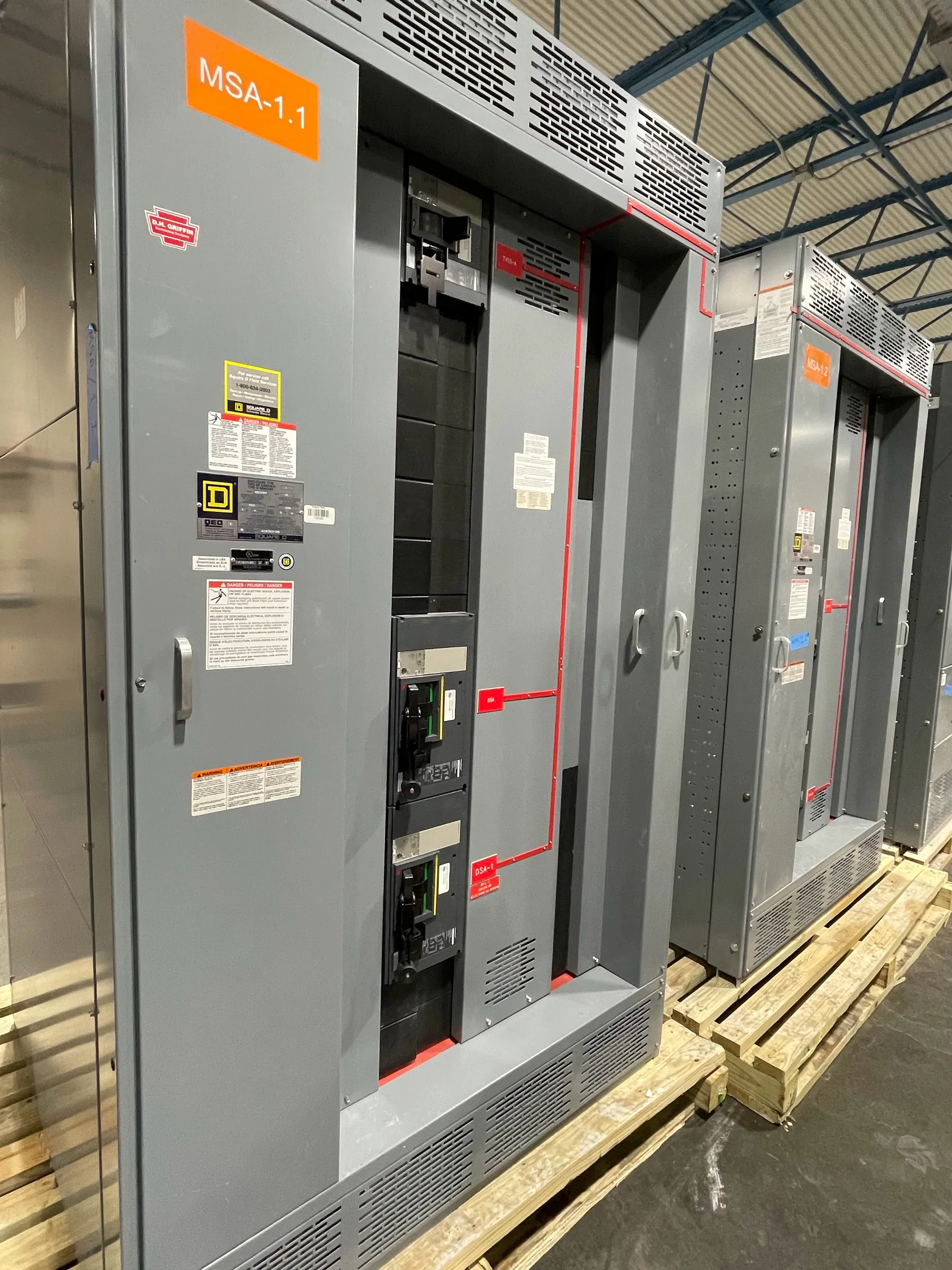
Define the Medium-Voltage System First
Medium-voltage switchgear controls and protects circuits between the electrical source and downstream distribution equipment. A new lineup for a Nevada project begins with the actual system, not a generic label: document the nominal voltage, frequency, phase arrangement, grounding method, source configuration, and intended service. These inputs help a U.S. manufacturer assess which construction is suitable for the specified duty.
Distinguish nominal system voltage from the equipment’s rated maximum voltage. The engineer must select the appropriate class using the applicable standard and the project’s operating conditions. Identify utility and on-site generation sources, normal and alternate operating modes, and whether any incoming or outgoing circuits will be reserved for future use. Each mode can affect the required electrical ratings and protective scheme.
Establish Fault Duty and Interrupting Requirements
A short-circuit study determines the duty that equipment and protective devices may face at their installation point. Provide available utility fault information along with transformer impedances, cable data, and any generator contribution. Where the system has multiple possible sources or switching states, the qualified engineer should evaluate relevant maximum and minimum fault conditions rather than relying on a single estimated number.
The assembly’s short-time and momentary withstand capabilities, and each breaker’s interrupting capability, address different aspects of a fault. Compare the required duty with documented ratings for the complete proposed construction and its devices. Future system changes can alter the duty, so state known expansion assumptions. A protective relay cannot compensate for equipment whose ratings are inadequate for the calculated conditions.
Select Insulation and Environmental Requirements
Insulation level must suit both the voltage class and expected overvoltages. The project engineer should identify the required dielectric withstand and basic lightning impulse insulation level, where applicable, in coordination with surge protection and connected equipment. A numerical voltage class alone is not enough to establish the necessary insulation level or the clearances for every interface.
Describe the installation environment early. Indoor electrical rooms, outdoor enclosures, and sites exposed to dust, heat, or altitude impose different design considerations. Confirm ventilation, corrosion exposure, condensation control, access, and any derating with the manufacturer. The proposed enclosure and ratings must be appropriate to the actual site rather than to a presumed Nevada climate or elevation.
Coordinate Relays, Instrument Transformers, and Controls
Protective relays use information from current transformers and, when specified, voltage transformers to recognize abnormal conditions and initiate tripping. Define the functions required by the protection study, the trip power source, alarm contacts, and communications interfaces. Current transformer ratios and accuracy requirements should support the intended protection and metering duties; they are not interchangeable simply because a transformer fits the enclosure.
Coordination with upstream utility protection and downstream equipment is a design task, not a preset feature of a switchgear lineup. Relay settings, breaker operating times, grounding, and the consequences of a loss of control power need review together. The electrical engineer and utility, where involved, should resolve the protection philosophy and any required approvals before settings are put into service.
Design Cable Terminations and Maintainable Access
Incoming and outgoing cable arrangements affect the section dimensions as well as field installation. Provide conductor size and quantity, insulation type, shield treatment, entry direction, bending space, and termination method. Also identify whether surge arresters, grounding provisions, or a separate cable compartment are specified. The manufacturer and installer should reconcile these details with the approved drawings.
Plan routes for cable pulling, inspection, and equipment handling alongside required working clearances. For withdrawable devices, consider the space and equipment needed to remove a breaker. Barriers and interlocks can support the intended operating arrangement, but they do not replace de-energization and verification procedures. Only qualified personnel should operate or work on the equipment under the applicable safety program.
Review Standards and Nevada Procurement Details
The applicable IEEE or other product standards depend on the medium-voltage construction and project specification. UL 891 is for applicable low-voltage switchboards; it should not be specified as the governing standard for medium-voltage gear. Request the proposed assembly’s documented ratings and any required evaluation or listing evidence without assuming that a standard reference proves certification.
For new U.S.-manufactured equipment serving Nevada, submit the one-line, fault study inputs, enclosure conditions, relay requirements, and cable schedule with the request. If all-American components are required, confirm sourcing for the actual bill of materials. Qualified electrical professionals must review the final design and interfaces, while the manufacturer confirms the construction and delivery schedule available for the approved scope.