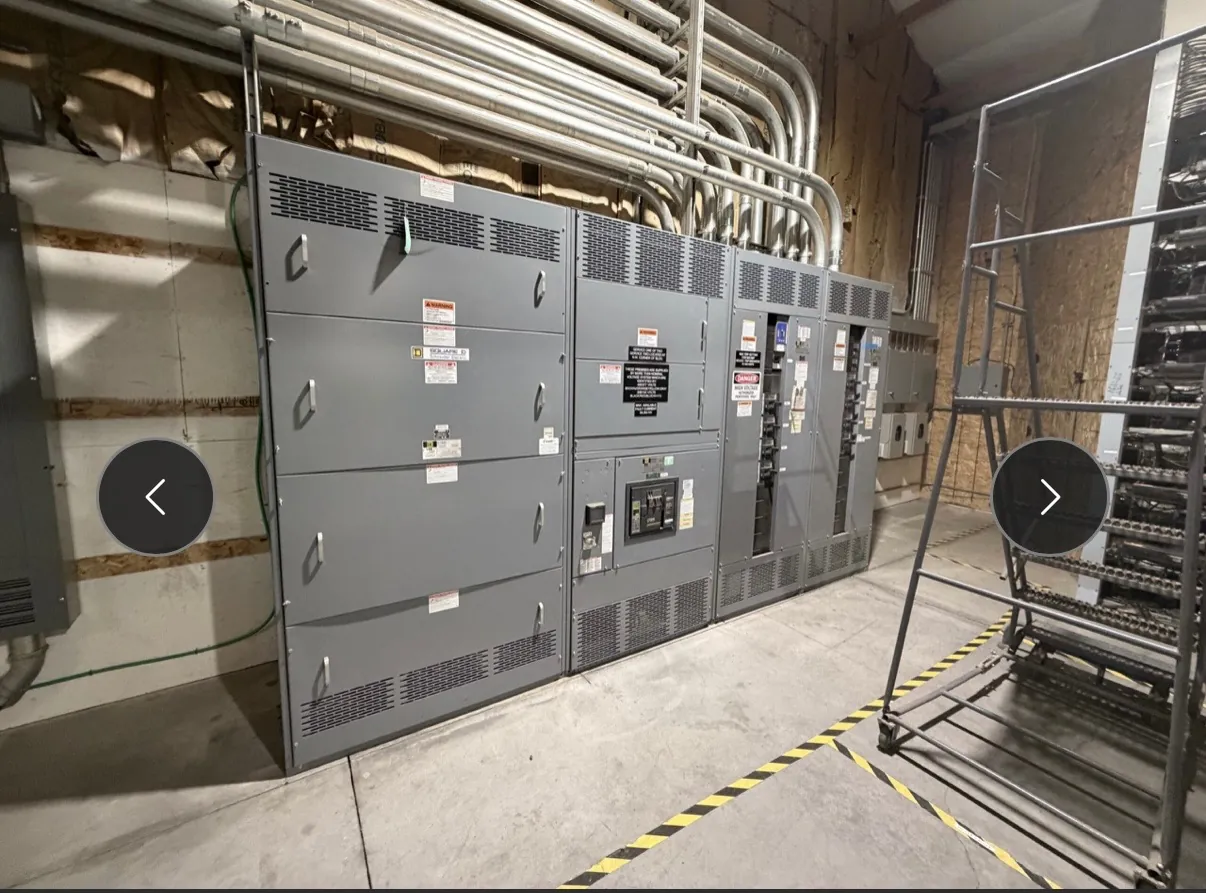
Begin With the Utility Service Arrangement
A service entrance switchboard is the point where an incoming utility service is arranged for metering, disconnection, and distribution to a facility’s loads. For a Nevada project, the serving utility’s requirements and the electrical design must be coordinated before the service section is finalized. A U.S. manufacturer needs the service characteristics and approved interface details to plan a new assembly.
Identify the service voltage, phase and wire configuration, supply location, expected load, and point of connection. Show the intended number of service sections and outgoing feeders on a one-line diagram. The serving utility, not a generic product description, determines its own metering and service requirements; local conditions and applicable codes also influence the final arrangement.
Settle Metering and Utility Access Early
Ask the utility whether the project requires self-contained or instrument-transformer metering, and who supplies the meter, transformers, test equipment, and enclosures. The answer affects compartment size, internal clearances, wiring paths, and responsibilities during installation. Establish whether the utility requires sealable sections, a particular sequence of metering and disconnecting equipment, or access to unmetered conductors.
Provide the manufacturer with the applicable utility drawings and identify which service-section details require utility review or approval. Verify meter location, access, identification, and any approved equipment or manufacturer requirements with the serving utility for the specific service area. A proposed layout should not be treated as accepted merely because it resembles one used elsewhere.
Locate the Main Disconnect and Plan Feeders
The main service disconnecting means allows the service conductors to be disconnected as required by the approved design and applicable code. Its type, rating, position, and identification should be coordinated with the utility’s metering arrangement and the facility’s distribution plan. Where multiple service disconnects are proposed, the engineer must verify the applicable rules rather than assume a particular arrangement is permitted.
Downstream feeder devices should be selected for the actual loads and connected conductors. Include any generator, transfer switch, photovoltaic system, or other source interface on the one-line, including the intended interconnection point. Such interfaces can change protective-device, metering, and labeling requirements. Specify spare positions only after checking the complete board’s space and rating limitations.
Coordinate Service Grounding and Bonding
Service grounding and bonding are distinct but related parts of the electrical design. Show the grounded conductor, grounding electrode conductor connection, equipment grounding provisions, and bonding arrangement on the design documents. The engineer must determine the proper location and method for the system bonding connection under the applicable code and the specific service configuration.
Prematurely assuming where neutral and ground connections belong can create an incompatible service section or field modification. Coordinate the available termination points, conductor sizes, utility rules, and any separately derived source with the electrical engineer and installer. The board’s ground bus and enclosure bonding must be compatible with the project grounding system and the manufacturer’s instructions.
Verify Available Fault Current and Switchboard Ratings
Obtain available fault-current information at the service location from the utility or the project’s engineering study. Compare it with the ratings of the proposed switchboard and the interrupting ratings of its protective devices. The complete assembly, devices, and any series-rated combinations must be documented and applied correctly; a single component label does not establish the rating of the entire board.
UL 891 is relevant to applicable low-voltage switchboards. If the specification requires a listed assembly, request evidence for the exact proposed service switchboard and its configuration rather than assuming that mentioning UL 891 establishes a listing. The project engineer should also review service load, short-circuit protection, coordination, and any required arc-flash assessment.
Secure Approvals Before Manufacturing Release
Submit the service layout, one-line, metering details, incoming conductor information, and equipment ratings for the reviews required by the serving utility and the authority having jurisdiction. Resolve comments before finalizing the service section, including cable entry, working space, and access for sealing or inspection. Manufacturer drawings, utility acceptance, and installation approval serve different purposes and should not be treated as interchangeable.
For a new U.S.-manufactured switchboard shipped to Nevada, state any all-American component requirement and verify the proposed sourcing. Share the jobsite delivery route and unloading constraints without assuming a specific schedule. Qualified electrical professionals must review the final design, and the contractor must complete the required inspections and coordination before the service is energized.