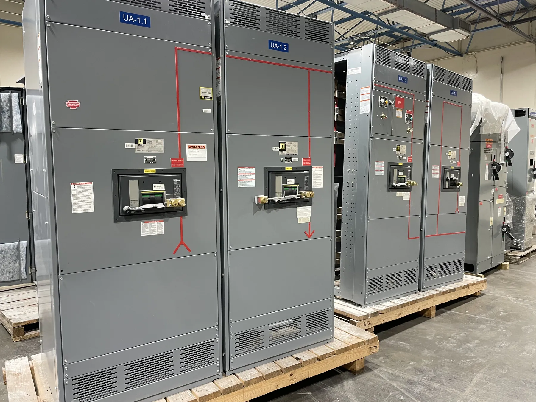
Panelboards Within the Distribution System
An electrical panelboard divides an incoming supply among protected branch circuits and, in some arrangements, downstream feeders. Its configuration should follow a load schedule and a coordinated one-line diagram. Nevada facilities can have very different distribution needs, from lighting and receptacles to equipment loads, so circuit count alone is not enough to select a new panelboard.
Determine system voltage, phase, frequency, grounding arrangement and the current needed for the connected and anticipated loads. The electrical designer should calculate loads and apply the relevant code provisions, rather than equating the sum of branch breaker handles with expected demand. Available mounting space and cable routes also influence a practical design.
Branch Circuits, Main Devices and Feeders
Prepare a circuit schedule showing load type, number of poles, conductor information and required protective device characteristics. Identify dedicated circuits, spare spaces and any special protection or monitoring specified for the installation. Separating loads by function can make the schedule clearer and support maintenance, but the resulting arrangement must still meet the project's electrical and operating requirements.
The incoming connection may use a main protective device or a main-lug arrangement, depending on the design and applicable rules. Coordinate the panel's bus and main ratings with the feeder conductors and upstream overcurrent protection. Space reserved for future circuits is useful only if the feeder, bus capacity, fault rating and physical arrangement can accommodate the proposed additions.
Finalize the circuit schedule as equipment selections develop. Confirm actual load currents and pole arrangements, and assign circuits to phases with the system's balance and neutral loading in mind. Locations such as kitchens, wet areas or spaces accessible to the public may introduce additional protective or installation requirements under the code adopted for the project. The responsible designer should determine which requirements apply rather than specifying the same device for every branch. During construction, changes in load location or protective devices should be reflected in the schedule and permanent circuit identification so that future service personnel can understand the installed arrangement.
Fault Current and Protective Coordination
The panelboard must be suitable for the available fault current at its installation point. That value is determined by the upstream supply and distribution system, not by the panel's load current. Review the short-circuit rating of the assembly and the interrupting ratings of protective devices against the calculated duty, including contributions and operating conditions identified in the project study.
Coordination with the upstream switchboard or other distribution equipment requires attention to device characteristics and settings. Selective operation is not automatic. Where a series-rated combination is proposed, use only an identified and permitted combination under the applicable rules and manufacturer instructions; do not infer an assembly rating from unrelated individual devices. Qualified review is essential to the protection and grounding design.
Enclosure and Installation Details
The enclosure should suit its actual surroundings. Indoor electrical rooms, outdoor locations and areas exposed to dust or moisture may call for different enclosure constructions. Specify the expected ambient conditions, mounting method and any security needs. Verify that the enclosure and installed devices have adequate space for conductors and terminations, with cable entry coordinated before fabrication.
Plan code-required working clearances, door access and a location that remains reachable after equipment and finishes are installed. Neutral and equipment grounding provisions should match the system design, including the effects of nonlinear loads where relevant. Circuit identification, field labeling and maintenance access are practical requirements to resolve on the drawings, not details to leave until the panel is energized.
Specifying New U.S.-Manufactured Equipment
A complete inquiry includes the one-line diagram, panel schedule, voltage, bus and main arrangement, fault duty, enclosure conditions and preferred breaker features. Check whether UL 67 is required for the panelboard and which other standards apply to the proposed devices. Ask for drawings and ratings for the actual assembly; a standard reference should not be treated as proof that every configuration is listed.
For equipment manufactured in the United States, clarify any domestic content requirements in the specification. If all-American components are important, define the covered parts and confirm their origin for the selected bill of materials. The final submittal should be reviewed by the responsible electrical professional and coordinated with the installer and authority having jurisdiction before construction proceeds.