277/480 V Service Entrance Switchboards: Confirm the Service Arrangement
A 277/480 V service entrance switchboard is a low-voltage assembly at the transition between the serving utility and a facility’s distribution system. The voltage designation describes the nominal system: 480 V between phases and, in a typical grounded wye arrangement, 277 V between a phase and neutral. It does not by itself establish the switchboard’s current rating, short-circuit rating, service configuration, or suitability for a particular site. Those details depend on the service, connected loads, and project requirements.
Before finalizing the service section, identify the utility’s metering requirements, the intended location of the service disconnect, the grounding and bonding arrangement, and the available fault current at the proposed connection point. These inputs influence equipment selection and how the service section interfaces with utility conductors and downstream distribution. Utility requirements and authority approvals vary; they must be confirmed for the specific project rather than assumed from the voltage alone.
Metering, Main Disconnect, and Service Interfaces
Utility metering can affect the switchboard’s layout, section arrangement, access requirements, and division between utility-controlled and customer equipment. Share the utility’s metering specifications and service drawings early, including any requirements for a meter compartment, instrument transformers, or a particular service entrance arrangement. The utility and project engineer should confirm which components belong in the assembly and how conductors enter and leave it.
The main disconnect must suit the service configuration and be coordinated with the downstream distribution plan. Relevant choices may include the disconnect type, overcurrent protection, available positions, and provisions for future distribution. Service conductors, grounding and bonding connections, neutral connections, and feeder exits all require coordinated space and termination details. The actual available configuration must be verified against the manufacturer’s equipment documentation and the project drawings.
Using 480 V Line-to-Line and 277 V Line-to-Neutral
A 277/480 V system can supply three-phase loads at 480 V line-to-line and compatible single-phase loads at 277 V line-to-neutral. Common design considerations include the balance of phase loads, the number and placement of feeder circuits, and whether lighting and motor loads are distributed across the same board or served from separate sections. The equipment schedule should identify each feeder’s voltage, phase, load type, protective device, and destination so the intended use is clear.
Motor feeders and lighting feeders have different load and protection considerations. Motor starting characteristics, operating patterns, and downstream protection affect coordination; lighting loads may include drivers or other electronic equipment with their own requirements. Do not infer feeder suitability solely from the nominal voltage. The engineer should confirm conductor and protective-device selection, load calculations, and applicable project criteria for each circuit.
Neutral Sizing and Grounding Details
Neutral requirements depend on the connected line-to-neutral loads and their characteristics, not just on the 277/480 V designation. The engineer should assess the expected neutral current, load balance, and any nonlinear loads that may affect neutral loading. That assessment informs the neutral bus and conductor requirements. Specify the intended neutral arrangement and connection details in the equipment documents; do not assume a standard neutral configuration will fit every facility.
Service grounding and bonding must match the system design and applicable authority requirements. Clearly document the grounding electrode system interface, service bonding points, neutral treatment, and any separation between service equipment and downstream distribution. These details are part of a coordinated electrical design, not choices that can be settled from a product description alone.
Available Fault Current, Ratings, and Coordination
Provide the available fault current at the switchboard’s service connection and its source, along with the protective-device information needed for review. The equipment’s short-circuit rating and the selected devices must be appropriate for the project’s conditions; a voltage rating does not establish either one. Confirm the applicable ratings, listings, and configuration in the equipment documentation. UL 891 applies to applicable low-voltage switchboards, but it should not be treated as a blanket statement about every product or project.
Coordination review should consider the service main, feeder protection, downstream equipment, and the facility’s operating objectives. Required selectivity, device settings, and fault-clearing behavior depend on the engineered system and the selected components. Final decisions require qualified engineering review, accurate source data, and site-specific information; they cannot be determined from nominal voltage alone.
Information to Provide for a Project-Specific Quote
For a useful quotation, provide the utility service requirements, one-line diagram, metering details, available fault-current data, load and feeder schedules, grounding arrangement, and preferred equipment layout. Include connection and cable-entry preferences, site constraints that affect access or installation, and any stated authority or project specifications. Note which requirements are confirmed and which remain subject to utility or engineer review.
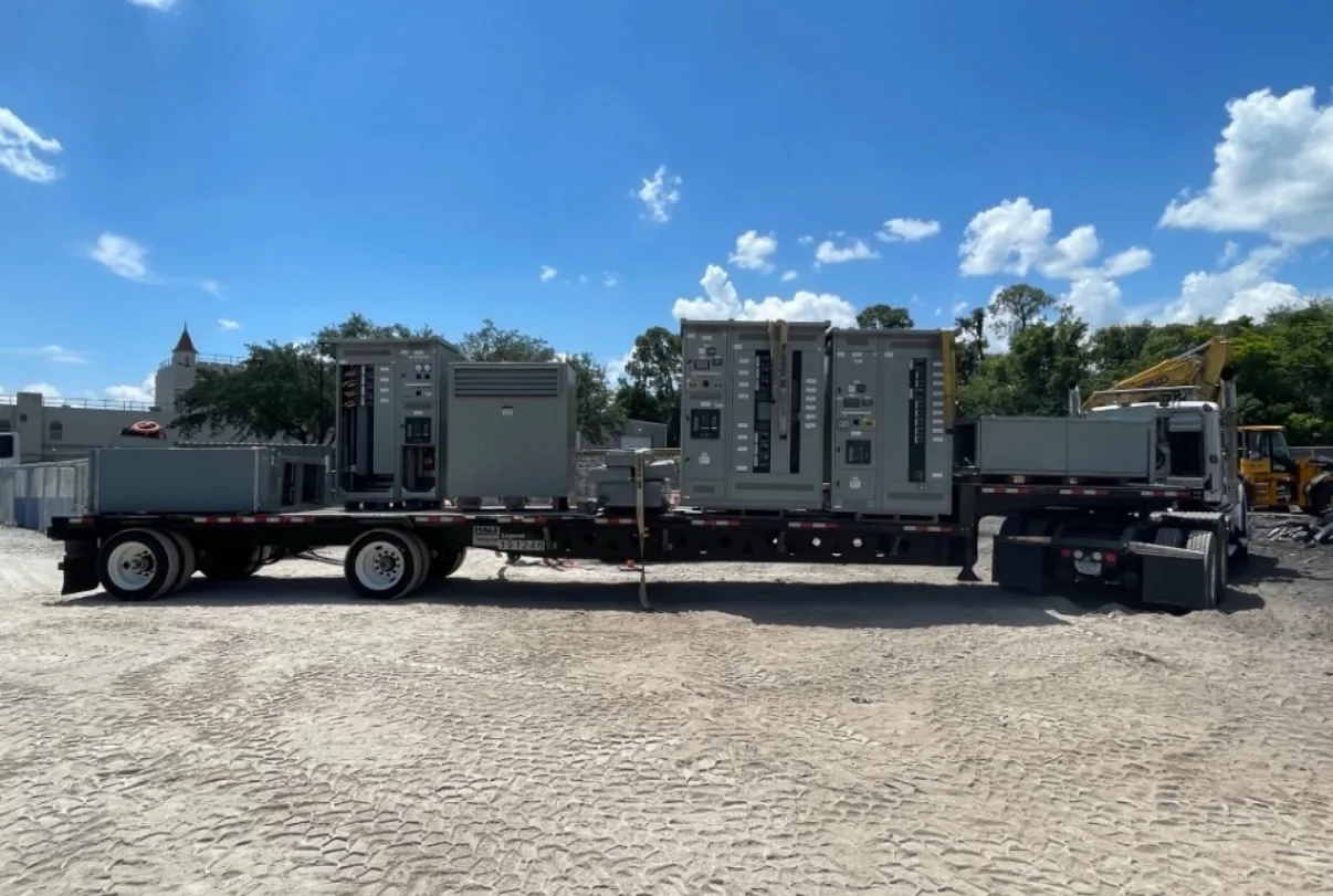
New custom switchboards are manufactured in the USA using all-American components, with short lead times supported and shipment available nationwide, including to Nevada. The final scope, schedule, and shipping arrangements depend on the approved project details and must be confirmed for the order. Clear engineering inputs help establish whether the proposed 277/480 V service entrance configuration, ratings, and interfaces match the facility’s documented requirements.