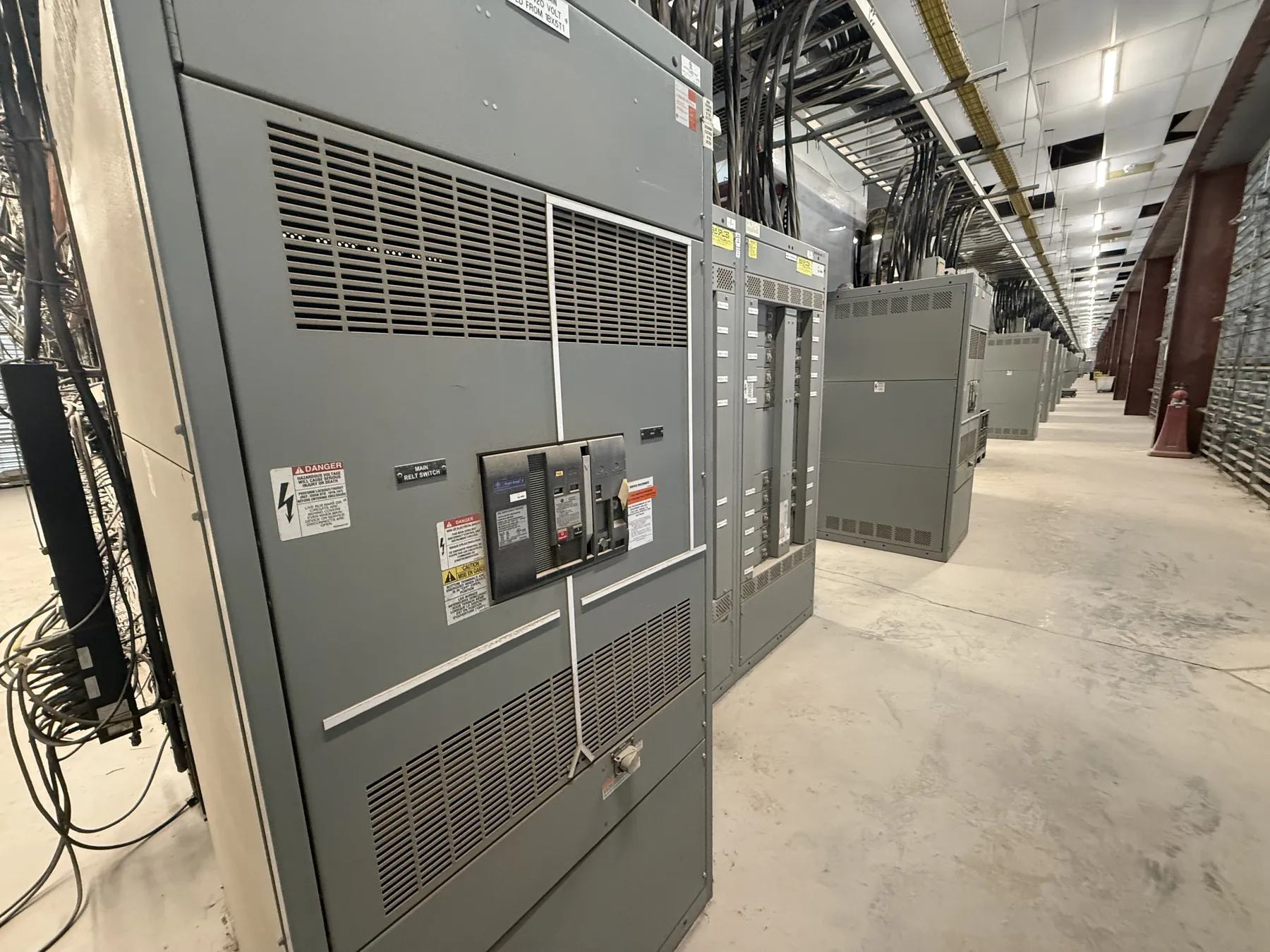
Mining Switchgear for Yerington, Nevada Operations
Mining power distribution has to suit the work being done at the site, not just a nameplate load total. For a Yerington project, begin with the equipment supplied by each switchboard or switchgear lineup: motor-driven machinery, process loads, lighting, auxiliary systems, and any connections to downstream distribution. A custom assembly can be arranged around the project’s feeder and motor duties, but its configuration and ratings must be established from the electrical design and confirmed for the actual site.
Our company manufactures new custom power-distribution equipment in the United States using all-American components and ships nationwide, including to Nevada. A quotation can be developed from the project’s one-line diagram, equipment schedules, and installation requirements. These inputs help distinguish what the mine needs from a generic equipment description and reduce the risk of overlooking interfaces that affect layout, protection, or future expansion.
Define Motor, Feeder, and Protection Requirements
Motor feeders may serve loads with different starting methods, operating patterns, and control interfaces. Identify each motor’s electrical data and intended control arrangement, along with any required provisions for starters, drives, or separate control equipment. The designer and equipment manufacturer can then coordinate the feeder arrangement with the selected components and the upstream and downstream system. A motor’s duty should not be inferred from horsepower alone.
For other feeders, provide the served load, conductor and connection requirements, expected operating conditions, and any project-specific protection criteria. Protective-device selection and settings depend on the system study, available fault current, equipment characteristics, and coordination with other devices. Those decisions require qualified engineering review; a switchgear quotation by itself does not establish that a protection scheme will perform as intended.
Specify the equipment’s required voltage, current and short-circuit ratings separately. A rating is not the same thing as the system voltage, and the appropriate values depend on the installation and design. Applicable listings and standards also need confirmation for the particular assembly and scope. UL 891 applies to applicable low-voltage switchboards; it should not be treated as a blanket designation for every switchgear product or voltage class.
Account for Dust, Ventilation, and Site Conditions — Mining Switchgear in Yerington, NV
Mining facilities can expose electrical equipment to dust, process residue, changing temperatures, vibration, moisture, or other environmental conditions. The actual hazards vary by location within a site. Describe where the lineup will be installed, what contaminants or environmental exposures are expected, and whether it will be indoors, in an enclosure, or in another site-defined setting. That information helps the engineering team evaluate enclosure needs, access, cooling, and the suitability of the proposed arrangement.
Ventilation is a practical design interface, not a detail to leave until installation. Room dimensions, airflow provisions, nearby heat sources, and the equipment’s specified environmental limits should be considered together. Dust-control measures may affect ventilation and enclosure choices, while enclosure choices can affect heat management and service access. Site engineers should confirm the environmental requirements and installation arrangement before equipment details are finalized.
Plan for Load Growth and Physical Expansion
Mining loads can change as operating areas, process equipment, or supporting infrastructure develop. For a Yerington project, record the planned load growth, the spare circuits needed for foreseeable additions, and the physical space available for future extensions. Indicate whether future capacity means unused feeder positions, provision for a lineup extension, or both. These are different planning needs and may affect the initial layout, bus arrangement, room footprint, and connection points.
Future provisions should be coordinated with the facility plan rather than assumed to be automatically available. Confirm access routes, working clearances established by the project design, cable entry locations, and room constraints with the responsible site and electrical teams. Any extension also depends on the original design, equipment compatibility, and a later engineering review. Capturing these constraints early gives the manufacturer a clearer basis for proposing an arrangement that fits the intended installation.
Coordinate Interfaces and Prepare a Useful Quotation Package
Useful quotation information includes the one-line diagram, load and motor schedules, specified ratings, protection requirements, enclosure and environmental criteria, cable and control interfaces, and the available room layout. Include known upstream-device information and downstream equipment requirements where available. Identify open design decisions rather than guessing; the project’s qualified electrical engineer can resolve them as the design develops.
For delivery to Yerington, share the jobsite location, receiving access, unloading constraints, desired shipping coordination, and any site-specific delivery requirements. These details help plan shipment without implying a local manufacturing facility or a particular delivery date. Short lead times may be supported, but timing depends on the finalized scope, component requirements, and project schedule. Clear technical inputs let the team assess the requested new assembly and coordinate its configuration with the conditions of the mining site.