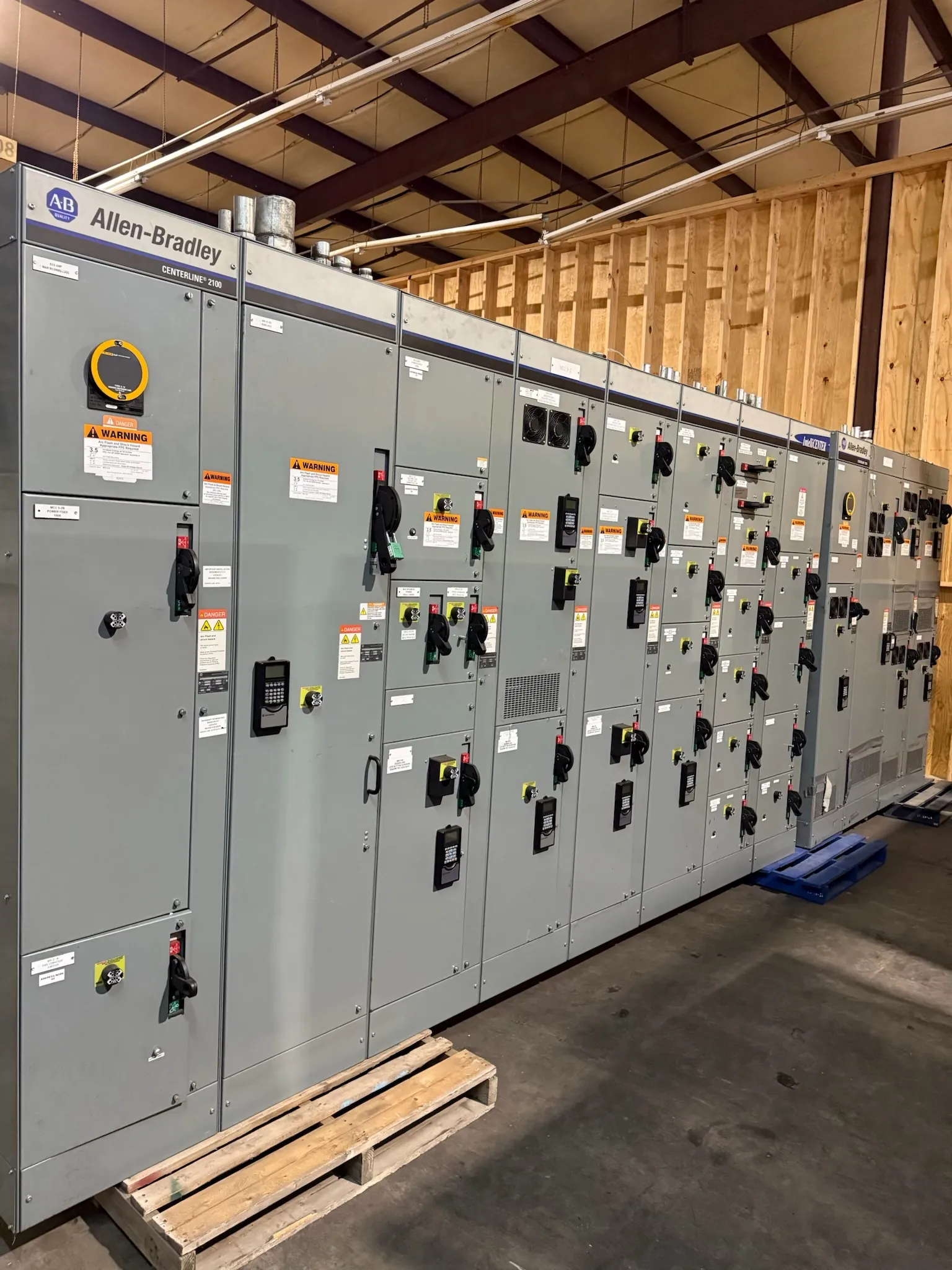
Power Plant Switchgear Planning for Yerington, Nevada
Power plant electrical distribution has to reflect how a facility generates, transfers, and uses power—not just the nameplate rating of a generator. For projects in Yerington, the switchgear arrangement should be developed around the plant’s one-line diagram, operating modes, utility or other interconnection requirements, and the loads that must remain available during normal operation and outages. The equipment manufacturer can build new custom switchgear and power-distribution assemblies to defined project requirements; qualified electrical engineers must establish the system design and confirm site-specific suitability.
Begin with the boundaries between generator terminals, generator breakers, plant buses, transformers, auxiliary distribution, and the point of interconnection. Identify which equipment is included in the switchgear scope and which items are supplied by others. This avoids gaps in responsibilities for protection devices, metering, controls, interconnecting wiring, and physical interfaces. A clear scope also helps distinguish the switchgear assembly’s ratings from the system voltage and from the ratings of connected equipment.
Generator Connections, Protection, and Synchronization
Generator connection details affect bus arrangement, breaker selection, instrument-transformer requirements, protective relaying interfaces, and control wiring. The design team should document each generator’s electrical characteristics, intended connection point, grounding approach, and expected operating modes. Protection settings and schemes must be engineered for the actual generator, transformer, network, and interconnection—not assumed from a generic switchgear configuration.
Where synchronization is required, define which devices perform synchronism checks, which controls issue breaker commands, and how permissive or blocking signals are exchanged. These functions may involve switchgear, generator controls, protection relays, and plant supervisory systems. Their interface responsibilities and communication requirements need to be coordinated before fabrication. A switchgear quotation can identify provisions in the assembly, but it cannot establish a complete synchronization scheme without the engineering information and control-system boundaries.
Backfeed, Interconnection, and Operating Modes
Power can flow in more than one direction as generators start, stop, parallel, or operate alongside an external source. The project review should identify possible backfeed paths through bus ties, transformers, auxiliary connections, and interconnection breakers. Protection, metering, and switching arrangements must account for the conditions the plant is designed to encounter, including whether sources may operate in parallel and how isolation is achieved for planned work or abnormal conditions.
Describe each intended operating mode in plain terms: for example, generator operation with plant auxiliaries supplied from the plant bus, auxiliary power supplied from an external source, or a transition between sources. The engineer can then assess how breaker control, interlocks, protection, and source-transfer logic relate to those modes. Utility or interconnection requirements, where applicable, must be confirmed with the responsible parties; they should not be inferred from the equipment description alone.
Auxiliary Loads and Distribution Priorities
Plant auxiliary loads can include pumps, fans, fuel or water systems, controls, lighting, and other equipment essential to generation or shutdown. Provide the load list with operating and starting characteristics, voltage and phase requirements, expected duty, and any loads that must be separated or prioritized. This information helps the design team evaluate feeder quantities, breaker types, bus arrangements, and the division between main switchgear and downstream distribution equipment.
Not every load needs the same source arrangement or level of continuity. Identify which loads operate continuously, which are intermittent, and which require a distinct supply or transfer arrangement. Also note loads planned for later phases. Those choices influence present equipment space and bus configuration, but future provisions should be based on a realistic load-growth plan rather than an unspecified allowance.
Future Capacity, Spare Circuits, and Physical Space
For a Yerington project, record anticipated load growth, the number and type of spare circuits desired, and the space available for future extensions. A spare breaker position, an unused compartment, and an arrangement designed for later lineup expansion are not interchangeable provisions. The project documents should state which is intended, along with any limits imposed by the electrical room, access routes, structural openings, or adjacent equipment.
Site conditions also affect practical equipment selection and delivery planning. Provide available room dimensions, access and handling constraints, environmental conditions, and relevant installation requirements. These details help determine whether the proposed lineup and shipping configuration can be accommodated. Nationwide shipping is available from this U.S. manufacturer, but delivery planning depends on confirmed project logistics and equipment configuration.
Quotation Inputs and Engineering Coordination — Power Plant Switchgear in Yerington, NV
A useful quotation package includes the latest one-line diagram, load schedule, generator and transformer data, operating-mode description, protection and control requirements, interface boundaries, available fault-current information, and physical layout constraints. Include the planned load growth and requested spare circuits, not just the initial feeder count. Identify applicable specifications and any required documentation so the proposed scope can be reviewed against the project’s actual needs.
Each assembly is manufactured new in the USA using all-American components, with short lead times supported; the schedule for a particular project depends on its scope and confirmed requirements. Applicable ratings, product listings, and standards must be reviewed for the specific equipment and application. UL 891 applies to applicable low-voltage switchboards; it should not be treated as coverage for every switchgear product or voltage class. Final ratings, listings, coordination, code compliance, and suitability require confirmation by qualified engineers through project and site review.