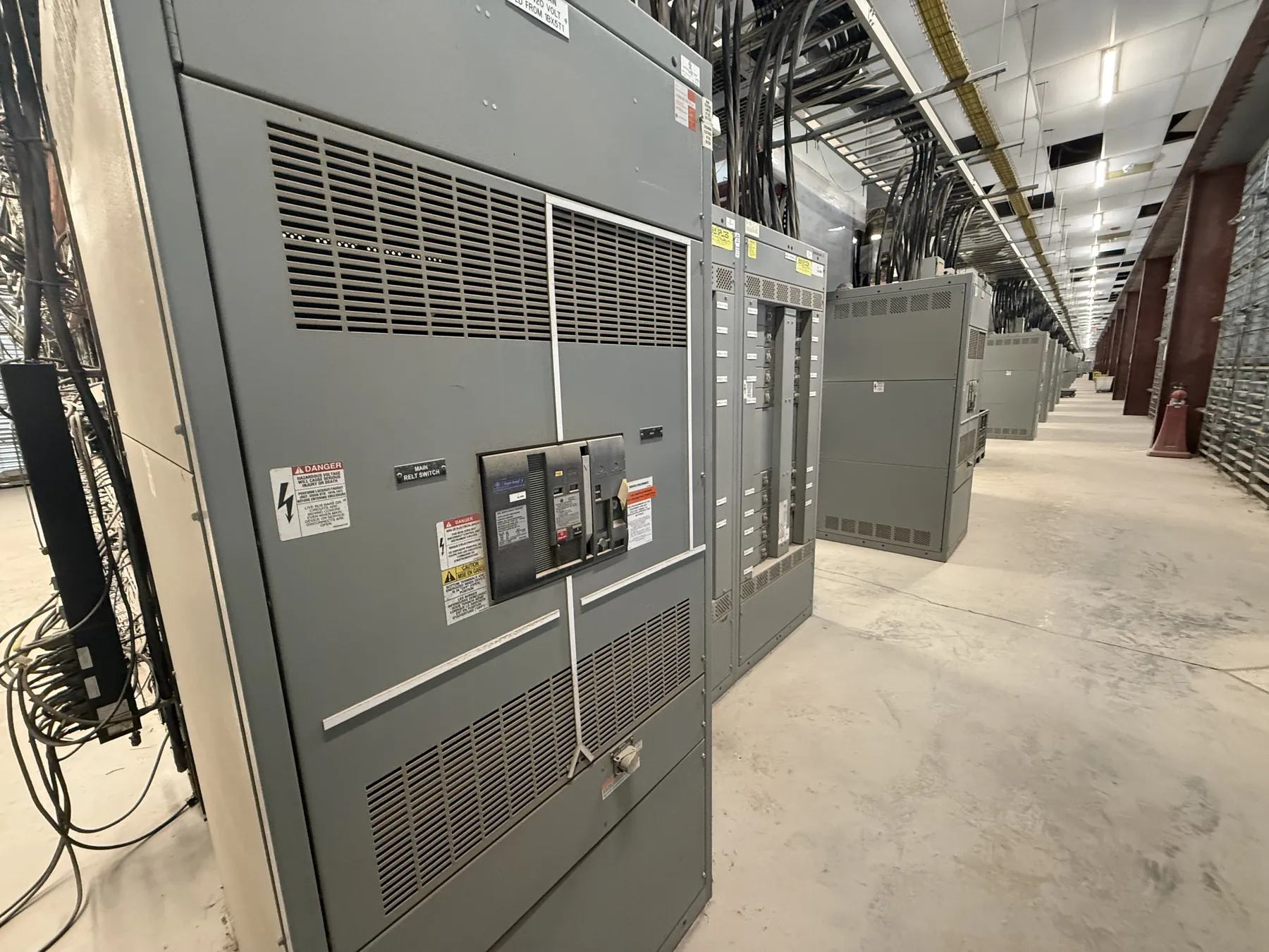
Service Entrance Switchboards for Winnemucca Projects
A service entrance switchboard is the point where a facility’s incoming electrical service connects to its distribution equipment. Its design needs to reflect more than the building’s load estimate: utility metering requirements, the service disconnect arrangement, grounding and bonding provisions, available fault current, and the authority having jurisdiction all affect the configuration. For Winnemucca projects, establish these interfaces early so the switchboard design can be coordinated with the utility service plan and the site installation schedule.
We manufacture new custom power-distribution equipment in the United States, using all-American components, and ship nationwide, including to Nevada. A project-specific review is necessary before confirming equipment ratings, construction details, listings, or delivery planning. The equipment must suit the approved electrical design and the conditions where it will be installed.
Coordinate Metering, Disconnects, and Service Boundaries
Metering requirements depend on the serving utility and the service arrangement. Confirm whether metering equipment is furnished or specified by the utility, where it must be located, and what clearances or access provisions apply. The switchboard layout may need space or compartments for the metering interface, but the acceptable configuration is not universal. Utility drawings and current service requirements should guide the design.
Also clarify where the service disconnect is located and how the service conductors enter the equipment. The number and arrangement of disconnects, the distribution sections downstream, and any provisions for future circuits affect the overall assembly. These choices should be reviewed by the project’s qualified electrical engineer and coordinated with the utility and relevant authorities rather than inferred from a general product description.
Grounding and Bonding Require Project-Specific Review
Service entrance equipment has grounding and bonding requirements that depend on the electrical system and the service configuration. The design team should identify the grounding electrode system, service conductors, bonding points, and any separately derived systems associated with the facility. That information helps determine how the service section interfaces with the building’s electrical design.
Do not assume that a standard arrangement will satisfy every site. The engineer of record must establish the grounding and bonding details, while the applicable authority reviews the installation under the adopted codes and project requirements. Share the approved one-line diagram and relevant grounding notes during quotation and design review to reduce the risk of mismatched equipment interfaces.
Confirm Available Fault Current and Equipment Ratings — Service Entrance Switchboards in Winnemucca, NV
Available fault current at the service point is essential information for selecting and coordinating equipment. Request the utility’s applicable fault-current data and provide it to the project engineer and equipment manufacturer. The switchboard’s short-circuit rating and other applicable ratings must be evaluated against the system conditions and the complete protection scheme. A rating is not the same thing as system voltage, and neither should be assumed from a building’s nominal service description.
Final selection also depends on voltage, phase, main-device requirements, distribution needs, conductor arrangements, and any specified environmental or enclosure conditions. Ratings, listings, and configuration details require confirmation for the specific assembly. UL 891 applies to applicable low-voltage switchboards; it should not be treated as a blanket statement covering every switchgear product or every installation.
Plan Winnemucca Receiving and Section Shipping — Service Entrance Switchboards in Winnemucca, NV
Switchboard sections can have practical limits for shipping, access, and placement. During planning, compare the proposed lineup dimensions and section breakdown with the route to the equipment location, including doors, corridors, staging areas, and any site-specific access restrictions. Confirm receiving hours, unloading arrangements, available equipment, and responsibility for moving sections from the delivery point to the installation area.
These logistics matter in Winnemucca just as they do at other project sites, but the appropriate plan depends on the actual facility and delivery route. Coordinate section dimensions and shipping splits with the project schedule, building readiness, and installation sequence. The manufacturer can review proposed sectioning against the equipment design, while the project team confirms access and handling arrangements at the site. Do not assume a particular unloading method or delivery date before those details are agreed.
Prepare a Clear Quotation and Design Package
A useful request for quotation includes the project one-line diagram, utility metering requirements, service voltage and system details, main and feeder requirements, available fault current, grounding notes, applicable specifications, and the required listing or code criteria. Include any dimensional constraints, indoor or outdoor location, cable-entry preferences, shipping-section limits, and the requested schedule milestones. If information is preliminary, identify it as such so open items can be tracked rather than treated as confirmed design inputs.
Our team can review the stated scope and develop a custom-manufactured switchboard proposal for the project. Before release, the design should be coordinated with the qualified electrical engineer, utility, installer, and applicable authorities. That process helps align the service interface, equipment arrangement, and Winnemucca delivery plan with the facility’s approved requirements.