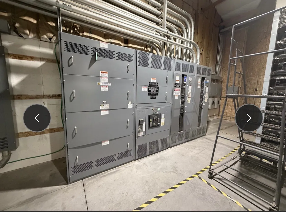
Manufacturing Switchgear for Winnemucca Production Facilities
Manufacturing facilities depend on electrical distribution that fits their production processes, motor loads and plans for expansion. A custom switchboard or switchgear assembly can bring feeders and protective devices together in a configuration suited to the facility’s electrical design. The right arrangement depends on the equipment served, available system information, operating priorities and installation constraints—not simply the building’s industry label.
For a Winnemucca project, early coordination should connect the facility team, electrical engineer, equipment manufacturer, contractor and installation schedule. Production areas may have different requirements for access, environmental conditions and acceptable downtime. Documenting those differences helps shape a practical equipment layout and identifies decisions that must be resolved before manufacturing.
Match Distribution to Production Loads and Motors
Start with an accurate load schedule. Identify production equipment, motors, support systems, expected operating patterns and planned additions. Motor starting and operating characteristics can affect feeder and protective-device selection, while simultaneous demand and load sequencing inform the overall distribution design. Existing drawings and field information should be checked for changes made since the original installation.
Controls and power distribution have related but distinct roles. A motor control center or other motor-control equipment may be appropriate for a group of motors, while a switchboard distributes power to downstream panels, machinery or other loads. The project engineer should define where these systems connect, what protection each requires and which functions belong in each assembly. Equipment selection should follow the engineered one-line diagram and confirmed system conditions.
Balance Uptime Priorities With Shutdown Constraints
Uptime planning begins by identifying which processes can stop together and which require a different shutdown window. Map the intended outage sequence, temporary operating arrangements if applicable, and the points where existing equipment must interface with new distribution. This gives the contractor and design team a basis for planning cutovers without assuming that a particular arrangement is safe or feasible at a given site.
Future feeder space is another planning tradeoff. Spare provisions may support later machinery, but their quantity, physical arrangement and electrical ratings need to be defined rather than treated as a generic allowance. Additional space can affect enclosure dimensions and shipping sections. The engineer should confirm which future loads are foreseeable and how much of the installation must be accommodated now.
Confirm Ratings, Protection and Equipment Interfaces
Equipment ratings are not interchangeable with system voltage. The project team should provide the nominal system voltage, available fault-current information, grounding configuration and other design inputs required to evaluate the assembly. Bus and protective-device ratings, interrupting capability, enclosure type and any required listing are project-specific and must be confirmed against the engineered design and applicable requirements.
UL 891 applies to certain low-voltage switchboards; it should not be read as a blanket standard for every switchgear product or voltage class. Whether a particular assembly is listed, and which standard applies, must be confirmed for the specified product and project. Connections to transformers, generators, transfer equipment, motor-control equipment and downstream panels should also be shown clearly so that interfaces are coordinated before release.
Plan Winnemucca Receiving and Section Shipping — Manufacturing Switchgear in Winnemucca, NV
Shipping and installation planning belong in the design conversation. Confirm the delivery address, site access, receiving hours, unloading method, laydown area, route into the electrical room and any limits imposed by doors, corridors or floor conditions. These details help determine whether an assembly can ship as a larger unit or needs to be divided into sections for transport and placement.
Section breaks involve more than truck dimensions. They affect handling, field joining, access to connections and the installation sequence. The contractor should coordinate the proposed shipping configuration with rigging plans and the final equipment-room layout. For a Winnemucca facility, weather exposure during receiving, travel distance from the delivery point and the site’s ability to store equipment securely may also warrant review, without presuming conditions at a particular property.
Provide the Inputs Needed for a Useful Quotation
A complete quotation request can reduce avoidable clarification and help align scope with schedule. Useful materials include the one-line diagram, load and feeder schedules, system voltage and fault-current data, equipment specifications, available room dimensions, required interfaces, shipping constraints and the target installation sequence. Identify expected future feeders and any required documentation or project-specific listing criteria.
As a U.S. manufacturer, we build new custom power-distribution equipment using all-American components and ship nationwide, including to Nevada. Short lead times are a stated capability, not a guaranteed delivery date: timing depends on the finalized design, component selection, approvals, production requirements and shipping plan. Confirm the current schedule and scope during quotation, then keep engineering, procurement and field teams aligned as project details develop.