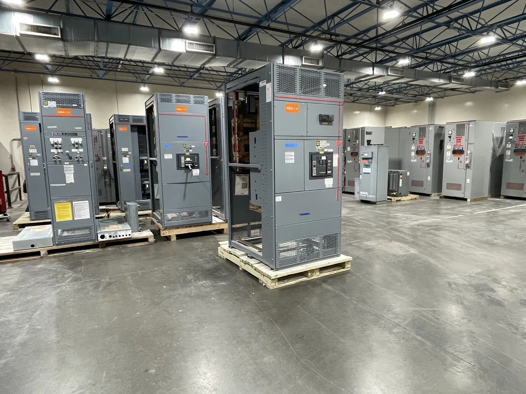
Switchgear for Manufacturing Production Loads
Manufacturing switchgear must fit the way a plant makes, moves, and monitors product—not just the total load shown on an electrical schedule. Production lines may combine large motors, variable-frequency drives, process controls, environmental systems, welding equipment, and ordinary building loads. Their operating patterns differ: some loads run continuously, some start in groups, and others cycle with a production sequence. Those distinctions help shape the distribution arrangement, feeder assignments, and coordination study.
Start by identifying which equipment depends on each distribution section and what a loss of power would mean for the process. A packaging line, ventilation system, furnace, and control network may have different priorities and restart requirements. Separating loads by function can make isolation and phased recovery more manageable, but additional sections, tie points, or alternate feeds introduce design and operating complexity. The useful arrangement is the one that reflects the facility’s actual process and electrical system.
Motor Controls, Drives, and Feeder Coordination
Motor loads influence feeder sizing, protective-device selection, and how a distribution system responds during starting and operation. For each significant motor, the design team needs relevant nameplate data and information about its starter, drive, duty, and expected operating sequence. A direct-on-line start, soft starter, and variable-frequency drive present different electrical characteristics; the appropriate approach depends on the motor, driven equipment, process requirements, and upstream system.
Drive-fed loads also make equipment interfaces important. Confirm how the switchgear connects to motor control centers, standalone drives, transformers, and process panels, including cable or bus connections and the available space for terminations. Harmonic performance and power-factor requirements may warrant engineering review when drives or other nonlinear loads make up a meaningful part of the plant load. These questions should be considered alongside protection and loading, rather than treated as details to resolve after the lineup is specified.
Uptime Priorities and Shutdown Planning
For a production facility, uptime planning begins with a practical account of what can stop, what can be interrupted briefly, and what needs an orderly shutdown. Identify essential process loads, control power, safety-related systems, utility services, and loads that can restart only in a particular sequence. That information can inform bus sectioning, feeder grouping, spare provisions, and any planned source transfer. Redundancy is not automatically beneficial: it can add equipment and coordination requirements, and it helps only when the complete system supports the intended operating scenario.
Replacement or expansion work also depends on the plant’s shutdown window. Before defining an equipment change, establish what existing gear serves, how it is connected, where tie-ins are possible, and which construction activities can occur while production continues. A workable sequence may require staged installation or a planned outage, but its feasibility depends on site conditions and engineering review. Do not assume an existing lineup can accept a new section or that a temporary arrangement is suitable without confirming the design and site constraints.
Future Feeder Space and Physical Fit
Allowing for future loads is most useful when the expected expansion is described. A plant anticipating another production line may need planned feeder positions, bus capacity, or room for a later lineup extension; an undefined allowance can be difficult to use and may add cost or footprint without solving the eventual need. Discuss likely load types, probable connection points, and the anticipated direction of expansion with the project engineer. Future space does not, by itself, establish that the installed equipment has adequate electrical capacity.
Room conditions matter too. Provide the equipment location, available floor area, access path, ceiling or overhead obstructions, ambient conditions, and nearby sources of dust, moisture, heat, or vibration. Include clearances and working-space requirements established by the project’s qualified design team. In an operating factory, access can be affected by conveyors, piping, stored materials, and production traffic. These details may influence lineup dimensions, entry and exit arrangements, enclosure selection, and the practical installation sequence.
Ratings, Protection, and Project Interfaces
Specify system voltage separately from equipment ratings. The project team must confirm the applicable voltage, continuous current, short-circuit rating, protective-device requirements, grounding arrangement, and environmental conditions for the actual installation. A rating is not a substitute for verifying compatibility with the facility’s available fault current and system design. Ratings, listings, product scope, and connection details require confirmation for the particular assembly and application.
Coordination also extends beyond the switchgear. Relevant interfaces can include the service or transformer, upstream protective devices, downstream motor control centers, generator or alternate sources, metering, controls, and plant monitoring systems. Share available one-line diagrams and protective-device information so qualified engineers can evaluate the complete arrangement. UL 891 applies to applicable low-voltage switchboards; it should not be interpreted as covering every switchgear assembly or other equipment category. Any required listing or standard should be confirmed against the specified product and project.
Information for a Manufacturing Switchgear Quotation
A useful quotation package identifies the facility and application, desired delivery schedule, system voltage, available fault-current information if known, one-line diagram, load or feeder schedule, motor and drive details, and planned sources. Include required lineup arrangement, cable or bus connections, metering and control interfaces, environmental conditions, footprint limits, and any expected future feeders. Note the outage window, installation phasing, and which existing equipment must remain in service. If details are incomplete, identify what is known and what needs engineering confirmation rather than assuming a rating or configuration.
Custom equipment is manufactured in the United States using all-American components and can ship nationwide, including to Nevada. The final design and schedule depend on confirmed project requirements and review. For a Nevada manufacturing site, coordinate shipping access, receiving arrangements, interior routes, and local facility conditions with the project team; these practical details help connect equipment planning to installation without assuming a particular site or delivery date.