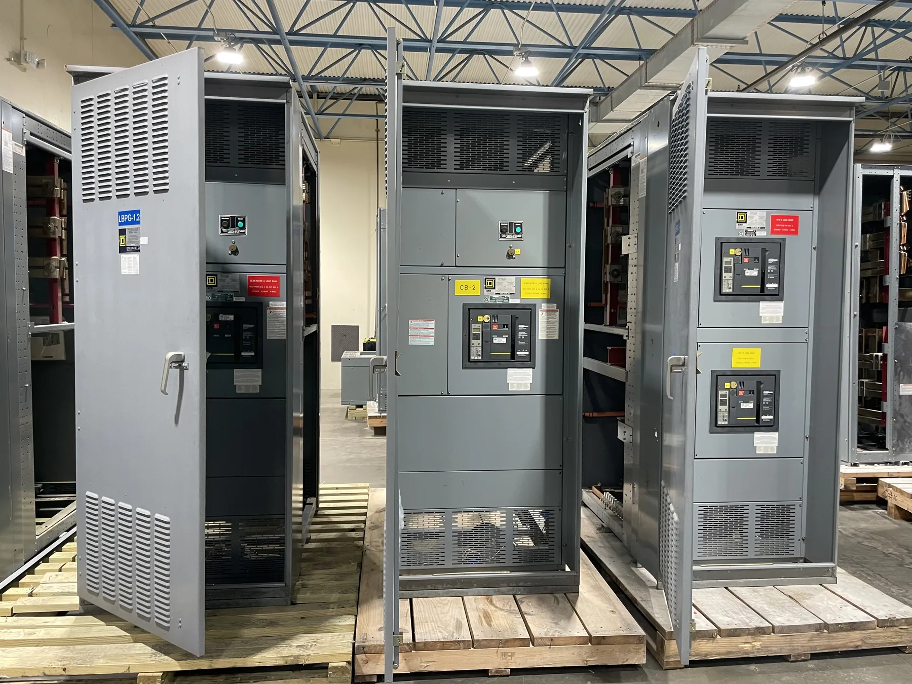
Medium-Voltage Switchgear for Winnemucca Projects
Medium-voltage switchgear is selected around the electrical system it must serve, not simply by a city name or a nominal voltage printed on a drawing. For a Winnemucca project, the first design discussion should establish the system voltage class, grounding arrangement, source and load configuration, and the equipment’s intended function. A lineup may serve incoming power, sectionalizing, transformer protection, motor feeders, or a combination of duties. Those functions affect the arrangement of compartments, switching devices, relays, metering, and cable access.
Our U.S. manufacturing operation builds new custom power-distribution equipment using all-American components and ships nationwide, including to Nevada. The project’s one-line diagram, specifications, and site conditions guide the configuration. The final design, ratings, applicable standards, and any required listing must be confirmed for the particular equipment and installation. Medium-voltage switchgear is not covered by UL 891, which applies to certain low-voltage switchboards.
System Voltage, Fault Duty, and Insulation Level
System voltage class and equipment ratings are related but are not interchangeable. The engineer should identify the system’s nominal and maximum operating voltage, grounding method, and expected operating conditions, then confirm that the proposed equipment’s voltage rating is suitable. Insulation level is a separate selection: it describes the equipment’s ability to withstand specified electrical stresses. It must be appropriate to the system and application rather than inferred from nominal voltage alone.
Available fault duty also needs project-specific review. The short-circuit current available at the switchgear depends on the source and network, including transformers, utility or generator contributions, and other connected equipment. The specified interrupting and withstand capabilities must be coordinated with that study and the protective-device scheme. Provide the latest fault-duty information available with the inquiry, and flag any planned source changes. A rating should not be selected from an assumed value or copied from unrelated equipment.
Protection, Relays, and Control Interfaces
Protective relays should match the functions the system requires. Depending on the design, those functions may include overcurrent protection, ground-fault protection, transformer or motor protection, metering, and communication with a plant control system. Relay model, sensing inputs, trip logic, control voltage, alarms, and communications protocol are all quotation and engineering inputs. These choices can influence compartment space, wiring, terminal points, and coordination with upstream and downstream devices.
Protection settings and selectivity are not determined by the switchgear manufacturer in isolation. The project’s qualified electrical engineer should review load data, fault-current study, transformer characteristics, downstream protection, and operating objectives. Provide the protection narrative or relay requirements where available. If the project has a preferred control scheme or needs interfaces to existing monitoring equipment, identify those requirements early so they can be evaluated against the proposed lineup.
Cable Terminations and Lineup Arrangement
Cable entry and termination details affect both the electrical design and the physical layout. Confirm whether incoming and outgoing cables enter from above or below, their conductor material and size, the number of parallel runs, phase arrangement, and termination hardware requirements. Also identify cable shielding and grounding practices, transition points, and any required space for stress-control components. The equipment design must accommodate the specified cables without assuming that a standard compartment will fit every termination.
Lineup configuration should reflect access, future connections, and the path from the source through the distribution system. Single-line drawings, equipment schedules, room plans, and cable information help establish the required sections and interfaces. Where the switchgear connects to transformers, bus duct, generators, or existing gear, provide the relevant connection details and dimensional constraints. These interfaces need engineering review; a visual match or similar equipment name does not establish electrical compatibility.
Winnemucca Receiving, Unloading, and Installation Planning — Medium-Voltage Switchgear in Winnemucca, NV
For delivery to a Winnemucca site, plan receiving and unloading alongside the installation schedule. Confirm who will receive the shipment, where a truck can access the site, what unloading equipment is available, and how each section will move from the receiving point to its final room or pad. Site access, door and corridor dimensions, turning space, floor or foundation conditions, and weather exposure can affect the practical delivery sequence. These are project conditions to verify, not assumptions that can be resolved from the destination city alone.
Before shipment planning is finalized, review section dimensions and weights, shipping splits, lifting provisions, and any restrictions on transport or site handling. Compare those limits with the route to the installation location and the resources scheduled to unload and position the equipment. Align the shipping sequence with foundation readiness, access availability, and the electrical contractor’s installation plan. Confirm the final section arrangement and receiving responsibilities before release so that delivery logistics support, rather than delay, the installation schedule.
Information for a Winnemucca Switchgear Quote
A useful request for quotation includes the one-line diagram, system voltage and grounding information, available fault-duty study, required insulation level, protective-device and relay functions, cable entry and termination details, lineup layout, and applicable project specifications. Include control power, metering, communications, environmental or enclosure requirements, and known site access constraints. Identify the required schedule and any sequencing or shipping limitations. Missing information can affect configuration and engineering review, so assumptions should be clearly marked for confirmation.
Each project’s ratings, construction details, standards, and any applicable listing require confirmation by qualified engineering review. With clear electrical and site inputs, a custom medium-voltage lineup can be developed for the intended Winnemucca application, with section shipping and receiving considered as part of the overall installation plan.