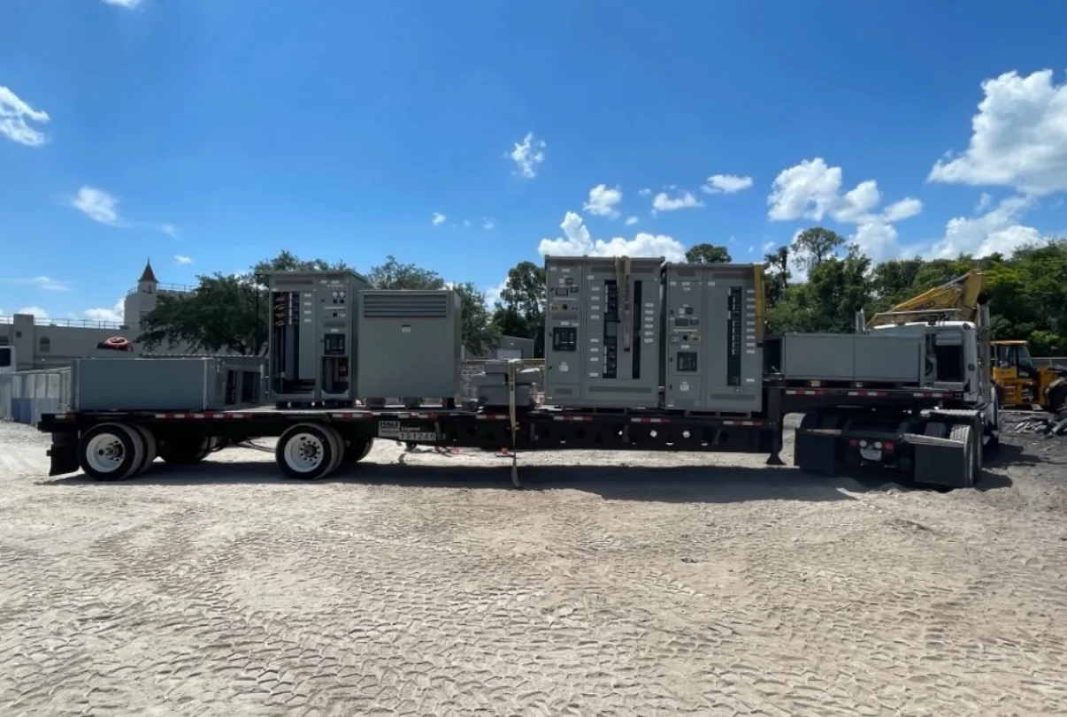
High-Voltage Substation Switchgear for Winnemucca Projects
High-voltage switchgear for a Winnemucca project is engineered around the substation’s electrical duty, utility interface and site conditions—not selected by location or a single voltage label alone. A project may require switching and protection at a utility interconnection, a customer substation or another part of a power system. The appropriate equipment arrangement depends on the system design and on what functions the switchgear must perform. We manufacture new custom power-distribution equipment in the United States using all-American components and ship nationwide, including to Nevada. The available construction must be confirmed against the project requirements before a design or quotation is established.
Early coordination is especially useful when equipment must fit an existing substation or connect to utility facilities. The one-line diagram, equipment layout, interface responsibilities and intended operating scheme help define the scope. A qualified electrical engineer and the relevant utility or system owner must establish and approve the design basis; a product description alone cannot determine whether a particular assembly is suitable for an installation.
Confirm Voltage Classification, Ratings and Insulation
Project teams should distinguish the system voltage from the equipment’s rated values. Voltage classification is only one part of the selection. The applicable continuous operating, insulation and short-circuit requirements depend on the system, the equipment configuration and the governing design criteria. Those values require engineering review and confirmation; they should not be inferred from a nominal voltage or copied from a different substation.
Insulation coordination is a project-specific consideration. The engineer may need to assess the system’s expected overvoltage exposure, grounding arrangement, connected equipment and protective devices when defining insulation requirements. Clearances, interfaces and the specified insulation level must suit the proposed construction and installation. The exact available high-voltage construction also needs confirmation during design development. Do not assume that a low-voltage switchboard standard or listing applies to high-voltage switchgear; UL 891, for example, pertains to applicable low-voltage switchboards, not every switchgear product or voltage class.
Protection, Switching Functions and Utility Interconnection
Protection requirements shape both the equipment scope and its interfaces. The project may call for specified switching functions, instrument transformers, relaying provisions, control wiring or communications connections, depending on the one-line and protection philosophy. These elements must coordinate with upstream and downstream devices and with the utility’s interconnection requirements. Relay settings, protective-device coordination and the final operating scheme are engineering matters, not assumptions that can be settled from a general equipment request.
For a Winnemucca-area interconnection, identify the serving utility or system owner, the point of connection and the party responsible for each interface. Share applicable interconnection documents, approved drawings, protection criteria and control requirements during the quotation and engineering process. IEEE or IEC requirements may apply depending on the project, specified equipment and governing authority. The applicable editions, scope and acceptance criteria should be confirmed with the project engineer and utility; citing a standard does not by itself establish compliance or approval.
Plan the Winnemucca Delivery and Site Constraints
Substation access and receiving arrangements belong in the schedule from the outset. Confirm the delivery route, gate and turning constraints, available staging area, unloading method, lifting access and the site’s ability to receive the planned shipment. Nevada weather and site exposure may also affect receiving, temporary storage and installation planning, but actual conditions must be assessed for the specific facility. The customer and installation team should confirm who provides unloading equipment, rigging and on-site handling.
Shipping limits can influence how an assembly is divided into sections and how those sections are handled at the destination. Discuss transport dimensions, section weights, access restrictions and the planned sequence of installation before finalizing the arrangement. Coordinate the shipping plan with foundation readiness, cable and bus interfaces, installation resources and the overall project schedule. Short lead times may be supported, but timing depends on the confirmed design, scope, manufacturing requirements and logistics; no delivery date should be assumed before review.
Information Needed for a Useful Equipment Quotation
A complete request helps establish a realistic scope and identify open engineering questions. Provide the available one-line diagram, system voltage and required ratings, substation layout, utility requirements, applicable IEEE or IEC specifications, protection and control expectations, environmental conditions, connection details, and receiving and unloading limitations. Include the required shipment configuration and target installation sequence if known. If some information is preliminary, identify it as such so it can be distinguished from approved project criteria.
Our team can review the requested configuration and clarify which construction and interfaces can be offered. Ratings, listings, standards, utility acceptance and project-specific details require confirmation; none should be inferred from a preliminary description. The final equipment selection and installation design remain subject to qualified engineering review and site coordination. With those inputs established, custom-manufactured equipment can be developed around the actual Winnemucca project rather than a generic substation assumption.