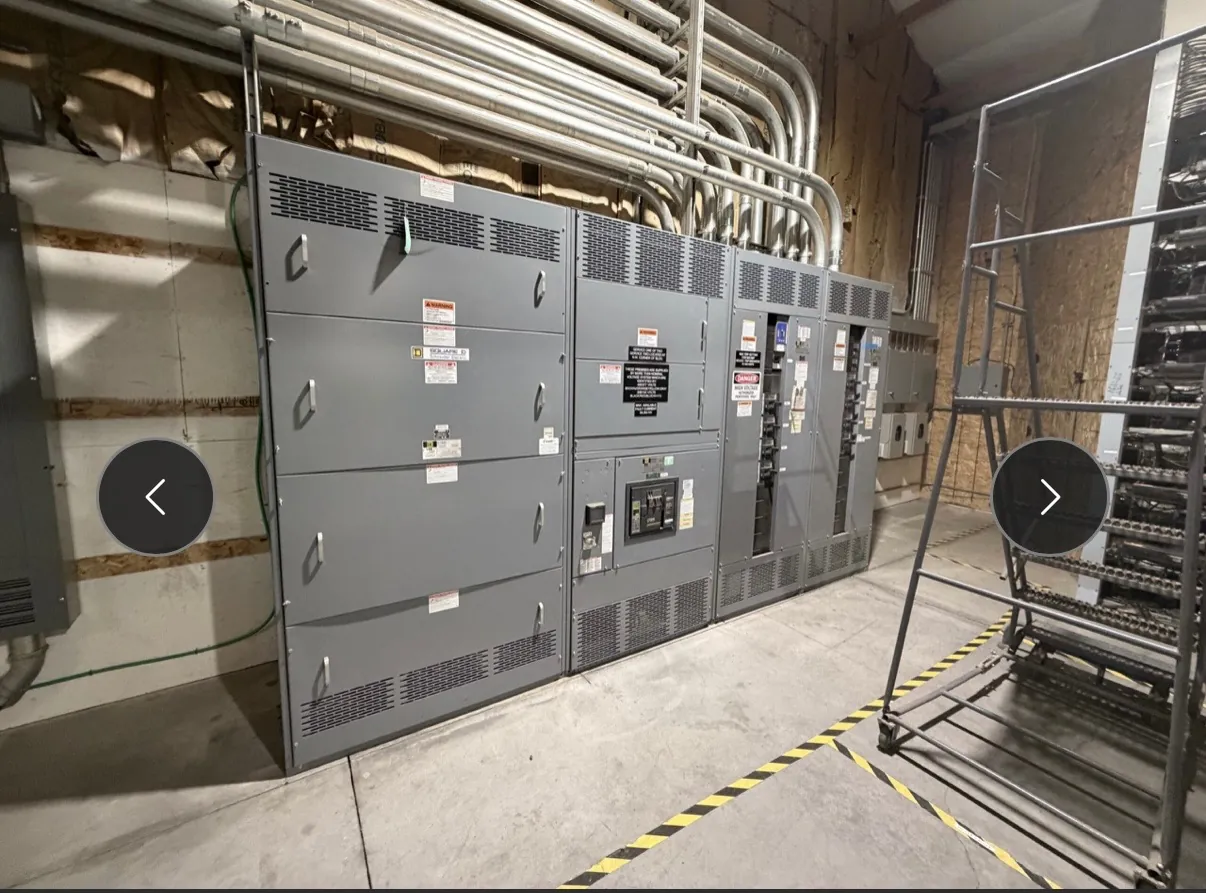
Service Entrance Switchboards for Reno, NV Projects
A service entrance switchboard marks the transition between utility service and a building’s electrical distribution system. For a Reno project, its configuration must reflect the utility metering arrangement, the service conductors, the main disconnect, grounding and bonding requirements, and the approvals required for that installation. These interfaces need to be resolved together: a change to meter location or service layout can affect the switchboard section arrangement, conductor routing, working clearances and coordination with downstream equipment.
We manufacture new custom power-distribution equipment in the United States using all-American components, and ship nationwide, including to Nevada. A quotation begins with the project’s actual electrical and site requirements—not a generic assumption about a “standard” service entrance. Final equipment selection, ratings and approval requirements must be confirmed for the specific design.
Coordinate Metering, Main Disconnect and Service Layout
Start by identifying who supplies and specifies the metering equipment, where it must be located, and how the utility expects the service conductors to enter and connect. Utility metering requirements vary by provider and project. The switchboard design should account for the required meter compartment or interface, access provisions, conductor landing space, and any separation between metering and service equipment. Confirm these details with the serving utility and the project’s electrical engineer before drawings are finalized.
The main disconnect configuration also affects the lineup. Its type, position, operating mechanism and relationship to distribution sections should suit the one-line diagram and installation constraints. Consider service conductor direction, feeder exits, equipment access and the route into the building. Changes made late in design can alter enclosure dimensions or require a different section arrangement, so these decisions belong in early coordination.
Establish the Service Rating and Available Fault Current
Specify the service voltage and phase separately from the equipment’s current rating. The project team should provide the electrical system characteristics, expected load, service conductor information and intended main-device configuration so the switchboard can be evaluated for the application. A rating is not a substitute for confirming that the equipment is suitable for the system or its operating conditions.
Available fault current at the service point is a key design input. The utility or electrical engineer should establish the applicable value and provide it for equipment evaluation. The selected equipment’s short-circuit withstand or interrupting characteristics, as applicable to its components and configuration, must be reviewed against that information. Coordination with downstream protective devices and the project’s overcurrent-protection design should also be considered. Do not assume fault-current suitability from a nominal voltage or ampere rating alone.
Plan Grounding, Bonding and Authority Reviews
Service grounding and bonding details depend on the electrical system, service arrangement and applicable project requirements. The one-line diagram and specifications should make clear where the service bonding connection is intended, how grounding conductors are routed, and how the switchboard interfaces with the building grounding electrode system. The responsible engineer must determine the design; the equipment layout should then provide the required connection points and space.
Identify the authorities and reviewers whose acceptance applies to the project, including the utility and applicable local authority having jurisdiction. Their requirements may affect metering, service disconnect placement, equipment access, labeling and submittal documentation. Applicable listings must be confirmed for the specific product and configuration. UL 891 applies to applicable low-voltage switchboards; it should not be treated as a blanket listing statement for every assembly or as a substitute for project-specific review.
Account for Reno Site and Environmental Conditions
Reno-area conditions should be verified at the actual installation site rather than inferred from the city name. Provide the equipment location, indoor or outdoor exposure, enclosure requirements, ambient-temperature design criteria and installation altitude. Compare the actual altitude and temperature assumptions with the equipment ratings and any applicable design adjustments. If the site has unusual dust, moisture, ventilation or space constraints, describe those conditions during quotation and engineering review.
Logistics also shape the installation plan. Confirm the route from the delivery point to the equipment location, access openings, handling limitations, final placement and required working space. These details help the project team coordinate the switchboard footprint and delivery sequence without assuming that every Reno facility has the same access or environmental conditions.
Prepare a Complete Quotation Package — Service Entrance Switchboards in Reno, NV
For a useful quotation, provide the one-line diagram, service voltage and phase, proposed ampere rating, available fault-current information, utility metering criteria, main disconnect requirements, grounding and bonding design intent, feeder and distribution needs, enclosure conditions, installation altitude and ambient-temperature criteria. Include drawings or specifications that identify space limits, conductor entry and exit directions, required interfaces, and authority review requirements. Note any project schedule constraints early; lead time depends on the finalized scope and current manufacturing requirements and must be confirmed for the specific order.
After the design inputs are reviewed, equipment details can be developed for project coordination and approval. Ratings, listings, dimensions, interfaces and schedule remain subject to confirmation against the completed design and site conditions. Clear early communication among the owner, engineer, utility, contractor and equipment manufacturer helps reduce avoidable revisions and keeps the service entrance aligned with the rest of the Reno project.