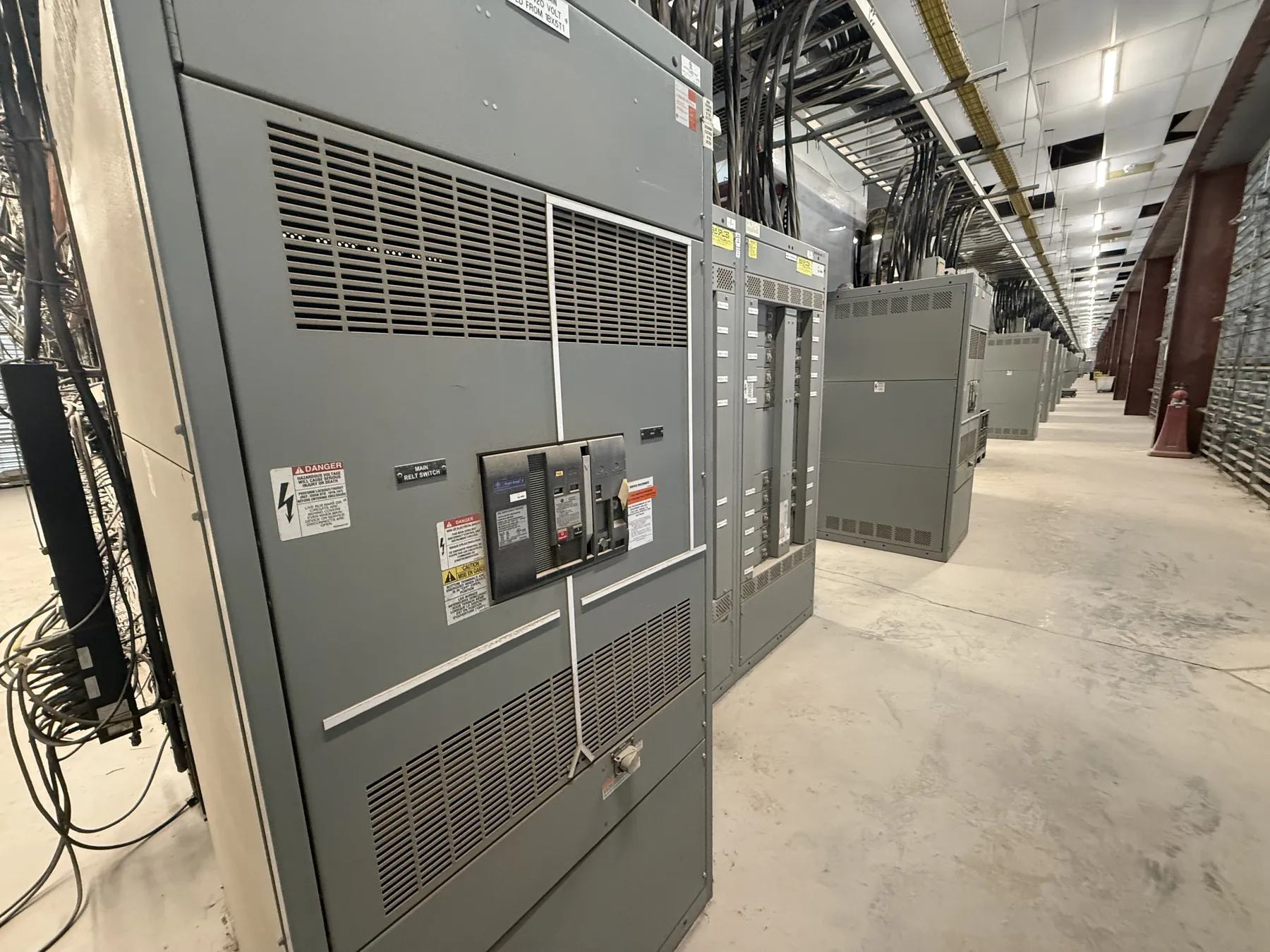
Planning Data Center Switchgear for Reno Facilities
Data center power distribution has to be designed around the facility’s load architecture, backup strategy and operating priorities—not selected from a generic equipment schedule. For a Reno project, begin with the intended electrical one-line, service characteristics and division of loads. Identify which systems must remain supported through a utility interruption, which can be shed, and how maintenance will be performed without creating an unintended interruption. These decisions shape the switchgear lineup, protective-device arrangement and interfaces with UPS and generator equipment.
Reno’s elevation and site-specific environmental conditions also belong in the design review. Confirm the installation altitude, expected ambient-temperature range, indoor or outdoor location, ventilation conditions and enclosure environment against the proposed equipment ratings and manufacturer requirements. Do not assume a catalog rating automatically applies unchanged to every site condition. The responsible electrical engineer and equipment manufacturer should review any derating or other design implications before equipment is specified.
Redundant Power Paths, UPS and Generator Interfaces
Redundant paths are useful only when the distribution design and operating sequence preserve the intended independence. The project team should document how utility sources, transformers, generators, UPS systems, maintenance bypasses and downstream distribution boards connect. Consider whether each path has separate upstream protection and routing, and whether a shared bus, tie, control circuit or physical space could become a common point of failure. A switchgear configuration cannot by itself establish end-to-end redundancy; the complete system architecture must be evaluated.
Define the electrical and control boundaries between switchgear and adjacent equipment early. Generator interface requirements may include the source arrangement, breaker functions, sensing and control signals, interlocking philosophy and coordination with automatic transfer equipment. UPS interfaces require similar clarity, including input, bypass and output relationships, maintenance isolation provisions and the expected response to abnormal source conditions. Exact arrangements depend on the engineered system. Equipment schedules and interface drawings should identify who supplies each device, control function and connection so that scope gaps do not appear during integration.
Selective Coordination and Protection Study Inputs
Selective coordination is a system-level objective, not a feature that can be promised from a switchgear description alone. Protective-device types, available fault current, conductor characteristics, transformer data, generator contribution and UPS operating modes can all affect the study. Provide the engineer with current source and equipment information, including utility data when available, transformer impedances, generator subtransient data, UPS fault-current behavior and downstream protective-device schedules. Study assumptions should reflect relevant operating configurations rather than only normal utility operation.
Review both the desired response to faults and the practical tradeoffs. Longer clearing times may affect equipment withstand requirements and arc-flash analysis; tighter coordination may constrain device choices or settings. The design team must reconcile applicable code requirements, the owner’s continuity objectives and the ratings of every affected component. Final protective-device selection and settings require qualified engineering review, project-specific study and field verification where applicable.
Maintainable Bypass Sequences and Operating Clarity
A bypass arrangement can support serviceability, but its value depends on a clear sequence and on the failure modes it is intended to address. Map the normal, transfer, maintenance and return-to-service states for the UPS and associated distribution. Identify which equipment remains energized in each state, which loads may be interrupted, and what electrical or mechanical interlocks are required to prevent incompatible source connections. Make the sequence understandable to the facility’s operators and consistent with the UPS manufacturer’s documented interfaces.
Also distinguish a maintenance bypass from redundancy. A bypass may permit service on a defined component, yet it can place loads on a different source path or reduce protection and resilience. The owner, engineer and equipment suppliers should agree on the operating philosophy, labeling, control responsibilities and any required status indications. Do not rely on a simplified diagram where the actual control scheme or connected loads create additional constraints.
Reno Project Conditions and Equipment Specification
For equipment serving a Reno site, coordinate delivery access, receiving space, indoor staging and the route from unloading point to the electrical room. Confirm doorway dimensions, turning clearances, floor loading limits and any restrictions on delivery hours with the facility team. These logistics can affect lineup segmentation and shipping configuration, but they do not replace electrical design review. Site conditions such as dust, moisture, temperature variation and ventilation should also inform enclosure and installation requirements.
Specify system voltage separately from equipment ratings. A rating describes a particular equipment capability; it is not a substitute for stating the project’s nominal system voltage, fault-duty requirements or operating conditions. If a low-voltage switchboard is under consideration, determine whether UL 891 is applicable to that specific product and configuration. That standard should not be treated as a blanket basis for medium-voltage equipment or every switchgear assembly. Confirm applicable listings, ratings, construction and project requirements for the exact equipment offered.
Information Needed for a Project-Specific Quote
A useful quotation package includes the one-line diagram, load and redundancy narrative, system voltage, available fault-current information, source and transformer data, UPS and generator interface requirements, preliminary protective-device schedule, installation conditions and requested listing or specification requirements. Include preferred lineup location, cable-entry direction, access constraints, environmental criteria and the intended maintenance-bypass sequence. Note which components are owner-furnished or supplied by other vendors.
Our U.S.-built custom assemblies use all-American components, support short lead times and ship nationwide, including to Nevada. Final configuration, ratings, listings, schedule and shipping details require confirmation against the project documents and site conditions. Early coordination among the facility owner, electrical engineer, UPS and generator suppliers, and switchgear manufacturer helps resolve interfaces before release for manufacturing.