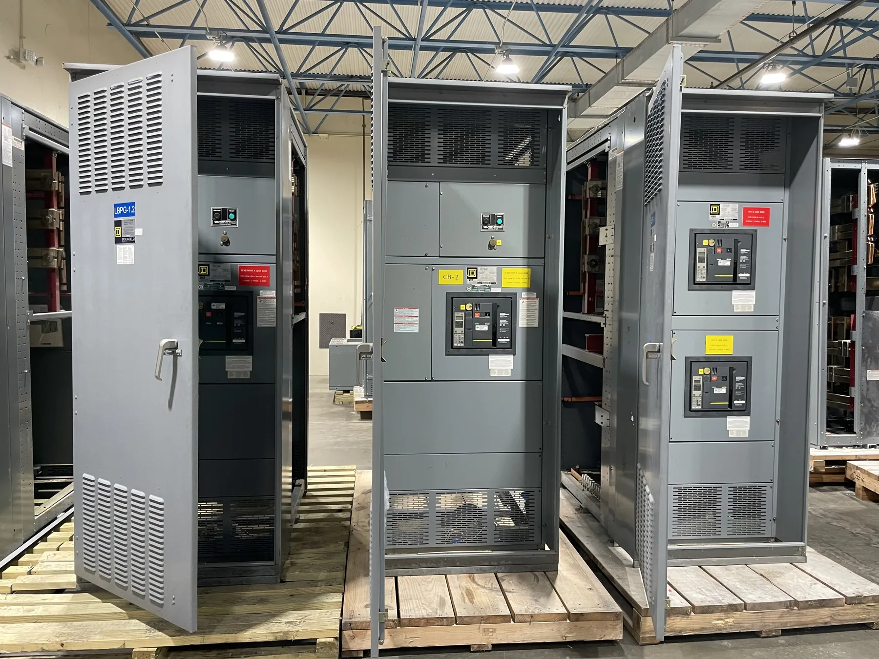
Data Center Switchgear for Redundant Power Paths
Data center power distribution is planned around the loads that must remain available and the paths intended to serve them. A switchgear lineup can be configured to support separate sources or distribution routes, but the equipment arrangement alone does not establish redundancy. Source independence, upstream utility arrangements, generator capacity, UPS topology, downstream panels, controls and facility operating plans all affect whether a path is truly independent. For a custom design, document the intended normal and alternate paths, which loads each serves, and what conditions permit a transfer. This gives the design team a practical basis for developing bus sections, source connections and tie arrangements without assuming that a particular topology fits every facility.
UPS, Generator and Utility Interfaces
Switchgear interfaces with UPS equipment and generators require clear definition of electrical and control boundaries. Identify whether the UPS input and bypass sources are separate, how its output connects to distribution, and whether a maintenance bypass is part of the overall arrangement or supplied as separate equipment. For generator connections, provide the source characteristics and describe the intended transfer scheme, including any required interlocks and control signals. Confirm the utility service configuration and available fault-current information with the responsible engineer and utility where applicable. These details influence connection provisions, protective-device selection and the physical division of the lineup. They also help avoid unclear responsibility between switchgear, UPS, generator and control-system suppliers.
Selective Coordination and Protection Planning
Selective coordination is a system-level design objective, not a feature that can be established by choosing switchgear in isolation. Protective devices must be evaluated across the relevant utility, generator, UPS and distribution operating conditions. Available fault current, device settings and characteristics, conductor data, equipment withstand ratings, and the behavior of alternate sources can all affect the coordination study. Provide the engineer with current one-line diagrams, source information and downstream device data when available. The study should identify the required coordination boundaries and any constraints on device selection or settings. Where a desired coordination result conflicts with other design objectives, such as limiting fault-clearing time or maintaining equipment ratings, the engineering team must resolve the tradeoff for the specific installation.
Maintainable Bypass Sequence and Lineup Layout
A bypass arrangement can support planned maintenance, but it introduces additional switching states and dependencies that need deliberate design. Define which equipment the bypass is intended to isolate, what continues to supply the critical load, and which sources may be connected in each planned state. The design team should translate the facility’s approved sequence into suitable interlocking, labeling, control interfaces and documented operating logic. This is not a substitute for site-specific procedures or qualified review. Physical layout matters too: consider access for inspection and maintenance, cable entry and routing, separation of sections where required by the design, and the space needed to connect the lineup. Review room conditions, environmental requirements and future expansion plans before finalizing dimensions.
Ratings, Construction and Quotation Inputs — Data Center Switchgear
Ratings must match the application and be confirmed against the system design. A voltage rating is not the same as the system’s nominal voltage, and current, short-circuit and withstand requirements depend on the equipment configuration and available fault conditions. Provide the intended system voltage, source and load information, one-line diagram, required lineup sections, incoming and outgoing connections, metering or control needs, and any specified enclosure or installation constraints. Identify project standards and the required documentation. If a low-voltage switchboard is being considered, UL 891 may apply to that product category; it should not be taken as a blanket standard for every switchgear assembly or for medium- or high-voltage equipment. Applicable ratings, listings and project requirements need confirmation during engineering review.
New Custom Equipment for Nevada Data Centers
We manufacture new custom switchgear and power-distribution equipment for data center applications, using all-American components and building assemblies in the United States. Short lead times are supported, with actual schedules dependent on the approved design, component requirements and project timing; no specific delivery date should be assumed before review. Equipment ships nationwide, including to Nevada. For Nevada projects, coordinate shipment planning with site access, receiving hours, unloading arrangements and the facility’s construction sequence. Temperature, dust, indoor or outdoor placement and other site conditions should also be stated so the proposed construction can be evaluated. A complete request package helps establish a practical scope and lets qualified engineers confirm interfaces, ratings and design details for the facility.