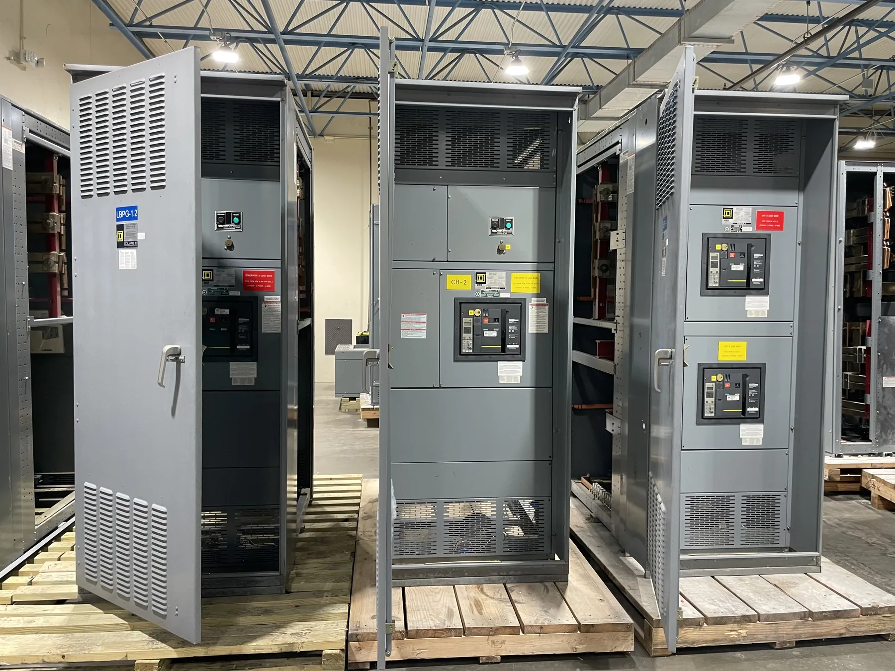
Planning Service Entrance Switchboards for Pahrump Projects
A service entrance switchboard is the point where a facility’s electrical service is received and distributed through its main service equipment. For a Pahrump project, its configuration should be based on the actual utility service, site conditions and authority requirements—not on a nominal voltage or a layout borrowed from another job. Early coordination helps establish where utility metering ends, where the customer’s equipment begins and how the main disconnect and distribution sections fit the building plan.
Our U.S. manufacturing team builds new custom power-distribution equipment using all-American components and can ship nationwide, including to Nevada. A useful first step is to confirm the project’s service characteristics and equipment responsibilities with the serving utility and qualified electrical design professionals. Those details affect the switchboard’s arrangement, ratings, metering provisions and interfaces.
Confirm Service Voltage, Metering and Ownership Boundaries
Provide the service voltage and system configuration stated for the site, along with the utility’s metering requirements. Voltage is a system characteristic; equipment ratings are separate selections that must suit the application. A switchboard rating should not be inferred from voltage alone. The utility may specify meter location, compartment arrangement, CT provisions, access or other service details. Confirm these requirements before the design is finalized, since a change to the metering interface can affect the section layout and enclosure dimensions.
Also clarify the ownership boundary and which party supplies or approves each component. The utility, electrical engineer, contractor and equipment manufacturer may have different responsibilities for metering hardware, service conductors, disconnects and related provisions. A clear one-line diagram and written utility requirements help prevent gaps between equipment scope and field work.
Choose the Main Disconnect and Distribution Arrangement
The main disconnect configuration depends on the service design, required switching arrangement and downstream loads. The project team should identify the intended main-device type and rating, the number and type of outgoing feeders, and any space or future provisions that should be included. Feeder quantities, conductor terminations and the physical direction of cable entry all influence the section design. If a project requires a particular access or working-space arrangement, provide that information with the drawings for review.
There are practical tradeoffs between a compact arrangement and one that allows more room for terminations or future changes. Larger conductors, numerous feeders, metering compartments and specified entry locations can affect section depth, width and placement. The final layout needs to reconcile the electrical design with the available equipment-room footprint and the planned path for service and feeder conductors.
Address Grounding and Available Fault Current — Service Entrance Switchboards in Pahrump, NV
The grounding approach must match the system design and applicable project requirements. Provide the grounding details identified by the engineer, including the intended service bonding arrangement and any specified grounding or neutral provisions. These decisions are interconnected with the service configuration and should not be selected from a generic product description. Qualified design professionals must evaluate the site and applicable requirements.
Available short-circuit current at the equipment location is another essential design input. The project team should obtain the applicable value from the utility or the responsible electrical engineer and identify any assumptions or study basis. The switchboard’s short-circuit rating and protective-device selection must be suitable for the system and coordinated with upstream and downstream equipment. Ratings, listings and coordination details require confirmation for the specific design; they cannot be established from a city name or service voltage alone.
Coordinate Approvals, Drawings and Site Conditions
Before release, identify the authority having jurisdiction and the utility approval process applicable to the project. Their requirements may affect metering provisions, equipment labeling, service-disconnect details or submitted drawings. UL 891 applies to applicable low-voltage switchboards; it should not be treated as a blanket statement covering every equipment type or configuration. Any listing requirement must be confirmed for the particular switchboard design and project scope.
For a Pahrump installation, provide the planned equipment location, access route, indoor or outdoor placement, enclosure requirements and conductor-entry conditions. Nevada heat, dust exposure or a remote site may be relevant when the project team defines enclosure and installation needs, but those conditions should be evaluated for the actual location rather than assumed. Shipping can be coordinated to the project destination; site access, receiving arrangements and any unloading constraints should be identified by the project team.
Prepare a Complete Quotation Package — Service Entrance Switchboards in Pahrump, NV
A quotation can be more useful when it includes the latest one-line diagram, service voltage and configuration, utility metering criteria, main-device requirements, available fault-current information, grounding details, feeder schedule, conductor-entry preferences and equipment-location constraints. Include the requested ratings and listing requirements, plus the authority’s review criteria when available. Flag unresolved items so they can be addressed before the design is treated as final.
We manufacture new custom service entrance switchboards in the United States, use all-American components and support short lead times, with shipment available nationwide. Final equipment scope, ratings, listings and schedule depend on confirmed project information and engineering review. For a Pahrump project, confirming utility interfaces, site fault current and grounding requirements early gives the design team a sound basis for developing a switchboard arrangement that fits the service and the facility.