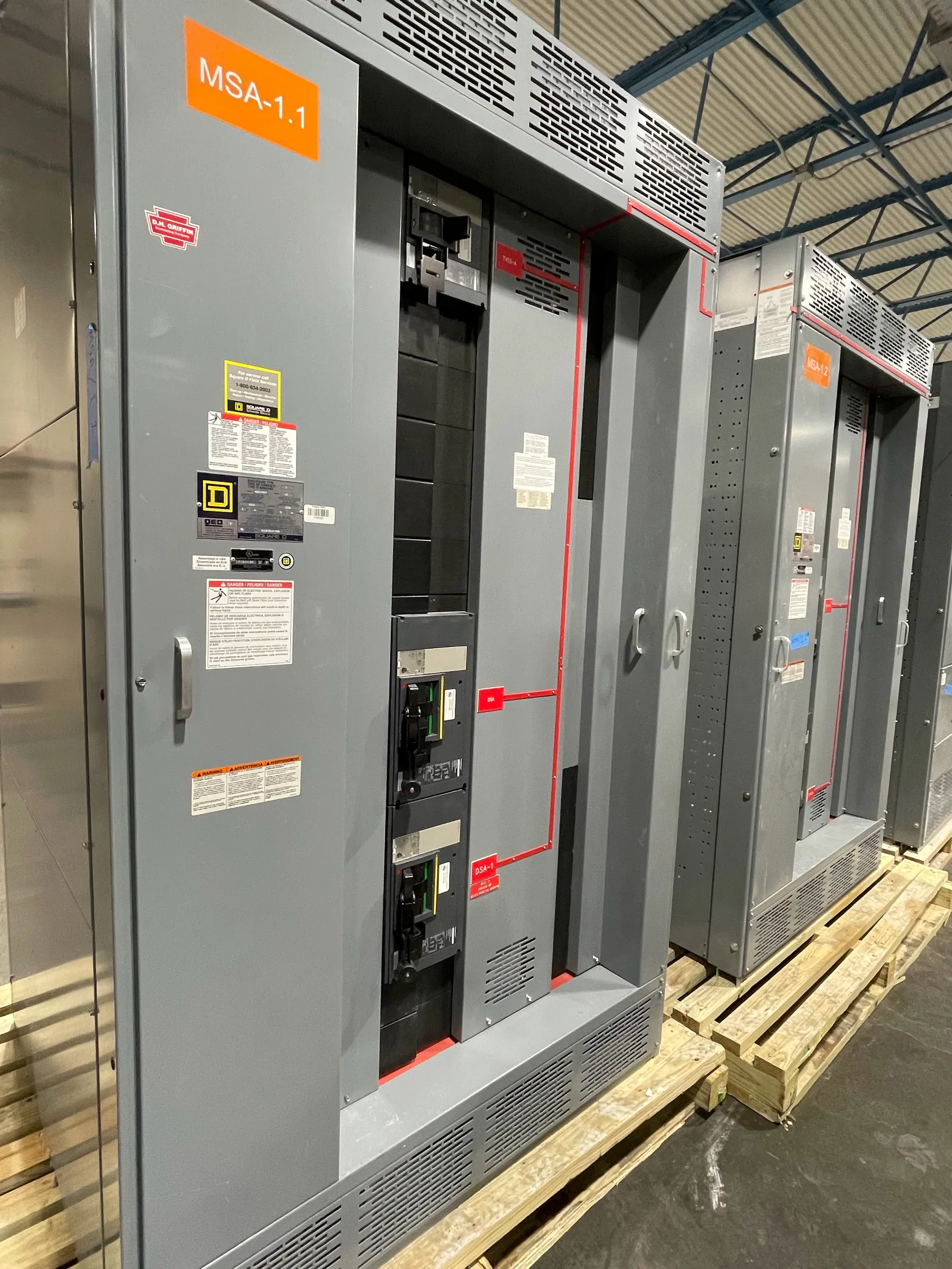
Planning Data Center Switchgear for a Pahrump Site
Data center distribution in Pahrump should be engineered around the facility’s actual service, load profile and continuity objectives—not a generic redundancy label. Early planning should identify the serving utility arrangement, service voltage, grounding approach and available short-circuit current at the site. Those conditions influence equipment ratings, protective-device selection, grounding and bonding details, and how the lineup connects to upstream and downstream systems. A manufacturer can develop a proposal for new custom equipment, but final design decisions require qualified electrical engineers and site-specific review.
For a Pahrump project, confirm the service and installation conditions with the project team before defining the switchgear arrangement. Site access, equipment-room dimensions, indoor or outdoor exposure, ventilation, cable-entry direction and the route from the service point can all affect configuration and installation planning. Nevada heat and dust may also inform facility-level environmental requirements; the equipment enclosure and installation approach should be selected for the documented conditions rather than assumed from the city name.
Redundant Paths and Transfer Boundaries
A redundant power path is only useful when its boundaries and operating purpose are clear. Project documents should show normal and alternate sources, the loads assigned to each path, and where transfer or isolation occurs. The arrangement may involve separate distribution sections, tie equipment or other project-specific switching provisions, but the one-line diagram and operating design must establish how sources interact. A tie that improves flexibility can also create risks if control logic, interlocking and operating states are not coordinated.
Discuss whether each path is intended to carry the full required load, only designated critical loads, or a defined portion under specified conditions. That distinction affects bus and device ratings, feeder allocation and the consequences of losing a section. The engineer should also identify any limits on paralleling sources and define how the system behaves during transitions, maintenance and abnormal conditions. These are design questions, not assumptions to settle from a product description alone.
UPS and Generator Interfaces
UPS and generator interfaces should be represented explicitly in the project’s electrical documents. Identify connection points, source relationships, bypass arrangements, transfer equipment and the distribution sections each system serves. UPS topology and operating modes can change how loads appear to upstream protective devices, while generator characteristics may differ from normal utility-source conditions. Those differences can affect fault-current analysis and protective-device performance, so coordination should consider relevant source modes rather than only the normal operating case.
Clarify which equipment is included in the switchgear scope and which interfaces are provided by the UPS, generator, transfer system or controls contractor. Define required control and status points, interconnection responsibilities, and any constraints on transition or synchronization. A maintainable bypass sequence should be developed with the complete system in view: the sequence, switching boundaries and required indications need to be reviewed by the responsible engineers and facility operators. Equipment copy cannot substitute for an approved operating design.
Selective Coordination, Fault Duty and Ratings
Selective coordination depends on the selected protective devices and their settings, the available fault current, the system configuration and the study criteria. Device curves should be evaluated across applicable source and operating modes, including generator operation where relevant. If alternate paths or ties can change the current contribution or protection zones, the study should reflect those states. The goal is to understand which protective device is expected to respond to a fault and how that response affects continuity to other loads.
Do not treat a voltage designation as a short-circuit rating, or assume that a rating follows automatically from a system’s nominal voltage. The specified equipment ratings and any applicable listing must be confirmed for the proposed product and project configuration. UL 891 applies to applicable low-voltage switchboards; it should not be taken as coverage for every switchgear product or for medium- or high-voltage equipment. Final ratings, listings and construction details require review against the project documents and applicable requirements.
Maintainability, Bypass Planning and Room Constraints
For a data center, maintenance planning should consider how a section can be isolated, what loads remain served, and whether the intended bypass changes protection or source conditions. Identify the components that require access, the space needed for equipment operation and service, and the cable or bus connections that constrain removal or replacement. Room layouts should account for the actual lineup dimensions, doors, working clearances and installation path; these details need confirmation with the project’s electrical and building teams.
In Pahrump, coordinate delivery and placement planning with the site’s access route, receiving area and construction schedule. Those logistics can shape shipping configuration and field assembly needs, but should not be mistaken for a promised delivery window. A new custom lineup can be developed to suit the documented arrangement, with all-American components and U.S. manufacturing; equipment can ship nationwide, and lead-time expectations should be confirmed for the specific scope.
Information Needed for a Pahrump Project Quote
A useful quotation package includes the current one-line diagram, load and feeder schedules, service voltage, grounding approach, available short-circuit current, and the project’s protection or coordination criteria. Include source details for utility, generator and UPS systems; tie and bypass requirements; specified device and bus ratings; enclosure and environmental conditions; dimensions, cable-entry preferences, and connection responsibilities. Note any required documentation or applicable product listing criteria, without presuming that a particular listing applies to every assembly.
When these inputs are incomplete, identify the open items rather than filling gaps with assumed values. The project engineer can confirm system design, fault-current data, coordination objectives and site conditions before equipment details are finalized. That disciplined exchange helps align the custom switchgear with the intended power paths and the practical constraints of the Pahrump facility.