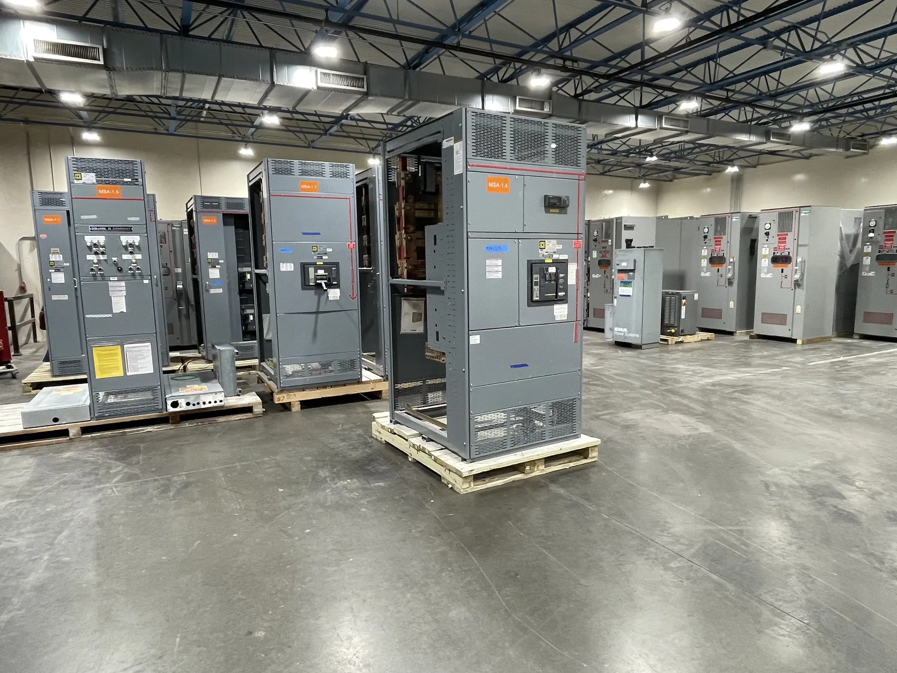
Medium-Voltage Switchgear for Pahrump, Nevada Projects
Medium-voltage switchgear is selected to suit the electrical system it will serve, not simply a city name or a nominal voltage on a drawing. For a Pahrump project, the starting point is the actual service voltage and the utility or upstream source information available for the site. The design team also needs to establish the grounding approach and available short-circuit current at the connection point. Those details shape equipment selection, protection, insulation coordination, and how the gear interfaces with transformers and downstream distribution.
We manufacture new custom power-distribution equipment in the United States using all-American components. Assemblies can be configured around project requirements and shipped nationwide, including to Nevada. A useful review begins with the one-line diagram, service and load information, and the project’s operating requirements. Equipment ratings, applicable listings, and configuration must be confirmed against the actual design and site conditions; they should not be inferred from a general product description.
System Voltage Class, Insulation, and Fault Duty
First distinguish the system’s operating voltage from the switchgear’s voltage class and equipment ratings. The nominal service voltage alone does not determine the complete specification. The design engineer must confirm that the selected gear is suitable for the system and its grounding method, and that its insulation level is appropriate for the expected electrical stresses and installation conditions. Insulation coordination may also require review of connected cables, transformers, surge protection, and other equipment.
Available fault current is another essential input. Switchgear must be evaluated for the short-circuit duty it may encounter, including the relevant interrupting and withstand requirements for the proposed arrangement. Source changes, transformer data, and the location of the equipment within the distribution system can affect that duty. A quotation based on preliminary fault information should identify what remains to be verified; final selection requires qualified engineering review rather than assumption.
Protective Relays and System Coordination — Medium-Voltage Switchgear in Pahrump, NV
Relay selection depends on what the system needs to detect and how the switchgear fits into the wider protection scheme. Project-specific considerations can include overcurrent protection, ground-fault detection, transformer protection, and coordination with upstream and downstream devices. The required functions, sensing inputs, control power, communications, and trip interfaces should be identified early so the equipment arrangement can support them.
Protection settings are not interchangeable product options that can be chosen without system information. They depend on the one-line, fault study, transformer characteristics, grounding method, load behavior, and coordination objectives. The responsible engineers should review the complete protection scheme and confirm settings and interfaces. Clear documentation of intended functions at the quotation stage helps distinguish the required relay package from features that may not apply to the project.
Cable Terminations and Physical Interfaces
Cable entry and termination details affect both the switchgear design and the installation plan. Confirm conductor type and size, cable count, termination style, phase arrangement, and whether cables enter from above or below. The cable manufacturer’s requirements and the termination components must be compatible with the selected equipment. Space for cable routing, bending, support, and access should be evaluated using the actual site layout and installation constraints.
Other interfaces deserve the same attention: incoming and outgoing connections, transformer or bus connections, grounding provisions, control wiring, metering, and any communications links. Room dimensions, door access, equipment orientation, and the path from delivery point to final location can influence enclosure sections and shipping configuration. These items are especially useful to resolve before fabrication, when changes to cable space or connection locations may affect the overall arrangement.
Planning for Pahrump Site Conditions and Delivery
Pahrump projects can differ substantially in service arrangement, building layout, and access to the equipment location. Share the site-specific information available, including indoor or outdoor placement, environmental exposure, room conditions, required enclosure characteristics, and delivery access. Nevada climate and dust exposure may be relevant to the installation environment, but the appropriate enclosure and equipment provisions depend on the actual location and project specifications.
Shipping to Pahrump is coordinated around the equipment configuration and project schedule; no delivery date should be assumed before those details are reviewed. Confirm unloading responsibility, receiving access, storage conditions, and the planned installation sequence with the project team. A U.S.-built assembly and nationwide shipping can support project logistics, but site readiness and installation coordination remain project-specific.
Information to Include in a Medium-Voltage Gear Request
A complete request helps align the proposed equipment with the electrical design. Provide the latest one-line diagram, confirmed or preliminary service voltage, grounding approach, available short-circuit information, load and transformer data, protection requirements, cable details, and the installation environment. Include required metering or communications, physical dimensions or room drawings, and any project specifications that govern interfaces. Identify open engineering items rather than treating preliminary values as final.
Medium-voltage switchgear is not specified under UL 891, which applies to applicable low-voltage switchboards. The correct standards, ratings, and any required listing depend on the equipment type and project requirements and must be confirmed for the proposed assembly. A qualified electrical engineer should review the design against the site conditions and applicable requirements. Once the project inputs are established, the equipment configuration can be evaluated for fit, protection, interfaces, and manufacturing scope.