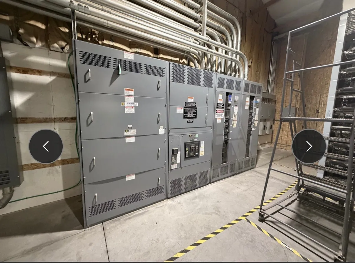
High-Voltage Switchgear for Pahrump Substation Projects
High-voltage switchgear for a Pahrump project must be selected around the electrical system it will serve, not simply a nominal voltage label. Substation arrangements can differ in incoming supply, transformer connections, feeder count, switching duties, grounding method and expansion plans. Those details affect the equipment configuration and its interfaces with protection, control and metering systems. Our U.S. manufacturing business builds new custom switchgear and power-distribution equipment; the exact high-voltage construction available must be confirmed during project review. We manufacture in the United States using all-American components, and ship nationwide, including to Nevada.
Confirm Voltage Classification, Insulation and Fault Duty
Start with the project’s service voltage and the equipment’s applicable voltage classification. These are related but not interchangeable: a system voltage alone does not establish the required equipment ratings or insulation coordination. The design review should identify the highest system voltage applicable to the installation, required power-frequency and impulse withstand levels, and environmental or altitude conditions that may affect insulation selection. The project engineer must confirm the governing criteria and applicable standards for the specific construction.
Available short-circuit current at the Pahrump site is another essential input. The equipment’s interrupting, making and short-time withstand capabilities must suit the system conditions and protective-device clearing times. A rating that appears adequate in isolation may not coordinate with upstream equipment or the utility’s fault-current assumptions. Ratings, construction, listings and standards applicability all require confirmation for the proposed assembly; they should not be inferred from a product category or a general voltage description.
Choose a Substation Arrangement Around the One-Line
The one-line diagram helps define whether the project needs an incoming section, transformer switching and protection, bus arrangement, outgoing feeders, metering, or provisions for future circuits. Bus configuration and sectionalizing choices can affect continuity, footprint, complexity and maintenance planning. For example, separating bus sections may support operational flexibility, while additional switching devices and protection zones add coordination work and interfaces. The right balance depends on the facility’s operating needs and the utility interconnection design.
Physical construction also matters. Indoor and outdoor applications impose different enclosure, access, environmental and installation requirements. Clearances, cable or bus entry direction, trench locations, lifting and handling constraints, and space for future work should be identified early. In Pahrump, the project team should document the actual site conditions rather than assume that a regional climate or a generic substation layout settles enclosure and insulation choices.
Coordinate Protection, Grounding and Utility Interfaces
Protection is a system-level design task. Relay functions, instrument transformer requirements, trip and close circuits, auxiliary power, control wiring and communications must align with the one-line and the utility’s interconnection criteria. Settings and coordination depend on the connected system, available fault current, device characteristics and operating philosophy. Qualified engineers should review protection zones, selectivity, backup protection and any transfer or interlocking functions; equipment selection by itself does not establish a complete protection scheme.
Grounding deserves equally specific review. Confirm the source and transformer grounding arrangements, ground-fault detection method, grounding electrode system and expected fault-return paths. These choices influence protective-device response, insulation requirements and the way equipment is connected to the site grounding grid. The utility and project engineer must resolve the intended arrangement and interface responsibilities before equipment details are finalized.
Apply the Right IEEE or IEC Requirements — High-Voltage Switchgear in Pahrump, NV
Applicable IEEE or IEC requirements depend on voltage class, equipment type, construction and project jurisdiction. The specification should identify the standards and editions required for the particular assembly, along with any utility criteria and project-specific tests or documentation. Do not assume that one standard applies uniformly to every high-voltage product or that a standard reference establishes a listing, approval or performance result. The engineering team and manufacturer should confirm the exact construction and compliance scope during technical review.
Prepare Pahrump Project Information for a Quotation
A useful quotation package includes the one-line diagram, service voltage, grounding approach, available short-circuit current and its source, protection requirements, equipment location, environmental conditions, interface drawings and applicable utility specifications. Include required bus arrangement, feeder count, control and communications needs, cable entry preferences, footprint limits and planned expansion where known. Identify who provides relays, instrument transformers, external cabling and field connections so responsibilities are clear.
For Nevada delivery, confirm the receiving location, access constraints, unloading arrangements and schedule milestones with the project team. These logistics can affect shipment planning, but a delivery date should be established only after the design scope and manufacturing schedule are reviewed. A technically complete package makes it easier to evaluate construction options, identify open engineering questions and determine whether the proposed switchgear can meet the project’s requirements.