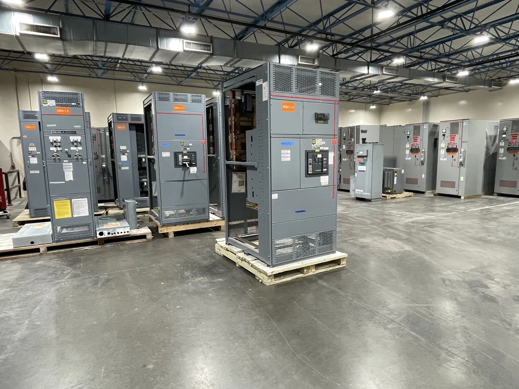
Medium-voltage switchgear for North Las Vegas projects
Medium-voltage switchgear connects and protects parts of a power system that operate above the low-voltage distribution level. For a North Las Vegas project, the equipment lineup should be defined around the actual utility or facility interface, load requirements, protection scheme and installation conditions—not selected by voltage label alone. We manufacture new custom power-distribution equipment in the United States using all-American components and ship nationwide. Project-specific design and equipment details require review against the site documents and the requirements of the responsible electrical engineer and serving utility.
Early planning is especially useful when equipment must fit an existing electrical room, a new building, or an outdoor installation. A lineup’s dimensions depend on its electrical arrangement as well as the space available for cable entry, terminations, access and future maintenance. In North Las Vegas, delivery access and the path from the receiving point to the final location should be reviewed alongside room conditions, rather than after dimensions have been fixed.
Define voltage class, fault duty and insulation requirements — Medium-Voltage Switchgear in North Las Vegas, NV
Start by identifying the system’s nominal voltage and the switchgear’s applicable voltage class. These terms are related but are not interchangeable: the system voltage describes the power system, while equipment ratings establish the limits for which the assembly is designed. The engineering review must also establish available fault duty at the point of connection and confirm that the proposed equipment ratings are suitable for the system and protection scheme.
Insulation requirements are another separate design input. The specified insulation level must suit the voltage class and the project’s electrical conditions. It should be confirmed from the one-line diagram, utility or facility criteria, and applicable engineering documents—not inferred from a product name or a rating copied from another installation. Fault duty, insulation level, enclosure arrangement and switching configuration should be considered together because changing one requirement can affect the equipment design and interfaces.
Match protective relays to the system coordination plan
Protective relays detect defined electrical conditions and initiate a protective response through the associated switching device. The relay functions, settings, instrument-transformer interfaces, control power and trip logic depend on the system design. They should coordinate with upstream and downstream protective devices so that the intended portions of the system are addressed under the conditions established by the project study.
For a quotation, provide the available protection documents where they exist, including the one-line diagram, relay requirements and coordination criteria. If settings or the final protection scheme are still being developed, identify that status rather than treating preliminary values as approved. The project’s qualified engineer is responsible for determining the required protection approach and confirming that it fits the facility and utility interfaces. A switchgear proposal should not substitute for a coordination study or site-specific engineering review.
Plan cable terminations and lineup interfaces
Incoming and outgoing cable details can materially affect compartment arrangement and overall lineup dimensions. Identify cable count, conductor information, termination type, entry direction and the location of each circuit. Confirm whether cables approach from above or below, where they transition into the gear, and what working space is available to route and terminate them. These details help the design team evaluate compartment layout and avoid assumptions that may conflict with the installation.
Map the cable routes at the North Las Vegas site, including the path from the source to the incoming section and from outgoing sections toward connected equipment. Note obstructions, changes in elevation, penetrations and any constraints on pulling or bending conductors. The final termination design must be checked against the selected equipment and cable requirements by qualified project personnel. Connection details, interfaces and ratings remain subject to confirmation as the drawings develop.
Fit the lineup to clearances, room conditions and delivery access
Before fixing lineup dimensions, document the electrical room or installation area and the clearances required by the applicable design, code and equipment instructions. Include doors, columns, overhead services, ventilation features and adjacent equipment that could affect placement or access. For outdoor equipment, provide the site conditions and enclosure requirements needed for engineering review; do not assume an indoor arrangement can simply be transferred outdoors.
Delivery planning also belongs in the layout discussion. Confirm the receiving area, access route, unloading constraints and movement path to the final location. Building openings, turns, floor transitions and staging space may influence how an assembly can be brought into position. These are site-specific logistics, not reasons to presume a particular delivery method. Sharing them early helps the equipment design and shipping plan reflect the real installation context.
Prepare a project-ready quotation package — Medium-Voltage Switchgear in North Las Vegas, NV
A useful inquiry for North Las Vegas medium-voltage switchgear includes the project location, one-line diagram, system voltage, required equipment ratings, available fault-duty information, insulation requirements, relay and control criteria, and incoming and outgoing cable details. Add lineup location, preliminary dimensions, clearance information, environmental conditions and delivery-access constraints. Identify governing project specifications and the status of utility or engineer review, and call out open items that still need confirmation.
With that information, the manufacturer can review the requested arrangement, identify questions and develop a project-specific scope for new equipment. Lead time depends on the finalized design, component requirements and production schedule, so timing should be confirmed during quotation rather than assumed. UL 891 applies to applicable low-voltage switchboards; it should not be used to characterize medium-voltage switchgear. Ratings, listings, interfaces and final dimensions must be confirmed for the specific project.