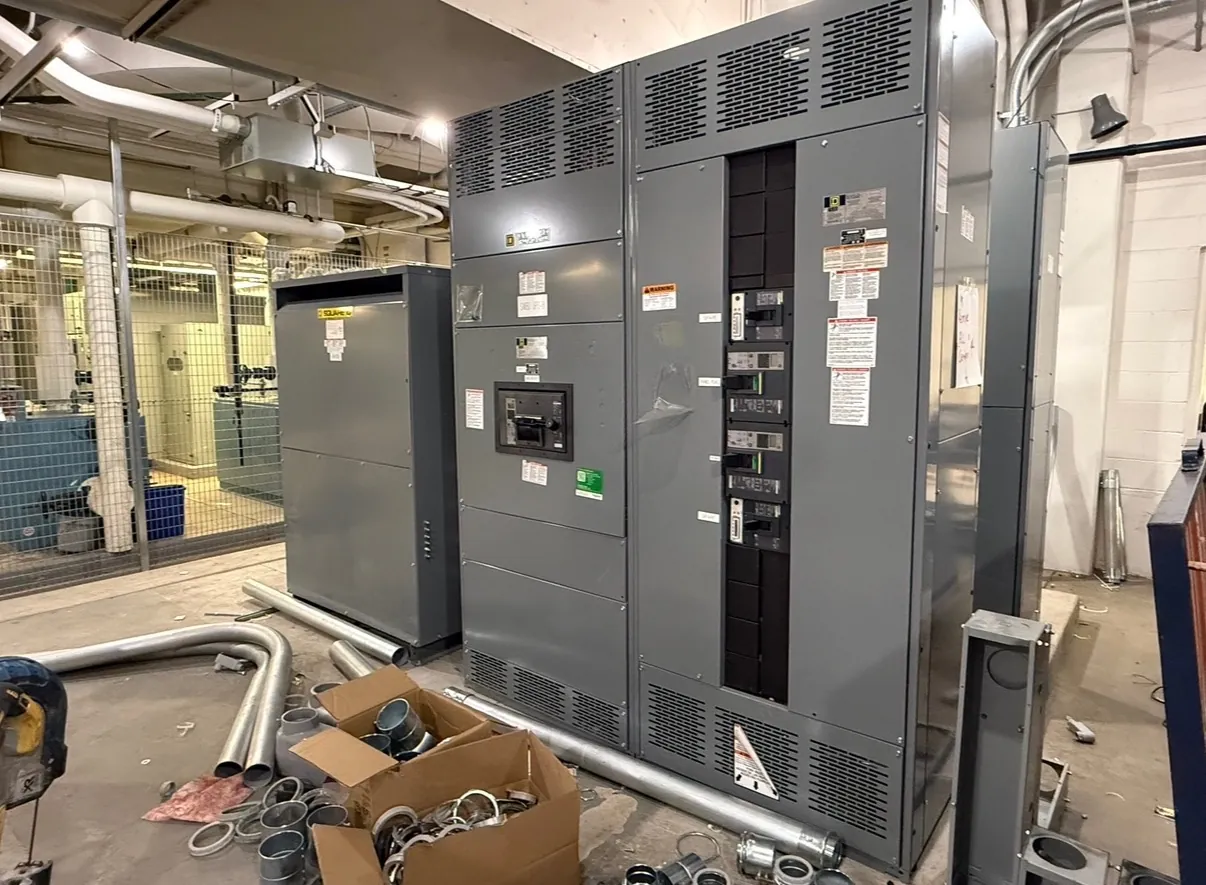
Planning Switchgear for a North Las Vegas Project
North Las Vegas projects can involve very different electrical environments, from commercial buildings and industrial facilities to additions within an operating site. The right equipment configuration depends on the project’s electrical design, service conditions and available installation space—not simply the city or building type. Our U.S.-built custom distribution equipment is made to project requirements and ships nationwide, including to Nevada. Early coordination helps align the switchgear lineup with the building, connected loads and delivery route before dimensions are finalized.
Start with the electrical one-line diagram and the project specifications. Identify the intended service and distribution arrangement, voltage, system grounding, available fault-current information, continuous load requirements and any future provisions. These inputs inform equipment selection, but they do not determine it on their own. The project’s qualified electrical engineer must confirm the design, applicable code requirements and coordination with the serving utility where relevant.
Map Cable Routes, Clearances and Delivery Access
Before fixing lineup dimensions, map incoming and outgoing cable routes from the equipment to their actual connection points. Show whether conductors approach from above or below, where they enter or exit, and how bends, pull space and cable-support arrangements affect the proposed sections. A route that looks clear on a one-line diagram may conflict with structural members, other building services or an existing installation once translated into the room layout.
Document the working space and access needed around the proposed lineup, along with doors, columns, walls, overhead obstructions and adjacent equipment. Confirm the manufacturer’s equipment dimensions and required clearances against the project drawings and applicable requirements. Also review the path from the receiving point to the final room: loading access, door and corridor widths, turns, floor transitions, lift arrangements and restrictions on delivery timing can all influence how equipment is configured and received. These are planning checks, not assumptions about a particular North Las Vegas site.
Choose a Configuration That Fits the Distribution Design
A custom lineup may include a main section, feeder sections, metering provisions or other specified functions, depending on the project. The engineer and equipment supplier should reconcile the one-line diagram, panel or feeder schedule, load information and physical arrangement so that each section has a defined purpose. Consider how many outgoing circuits are required, where they need to connect and whether the design calls for spare or future provisions. Any allowance should be shown in the project documents rather than inferred from an early equipment sketch.
Access and maintenance considerations can affect section placement and door arrangement. So can the direction of cable entry and the relationship between the equipment and nearby distribution components. If a room is constrained, compare layout options before the lineup is released for manufacture; changing section widths or connection arrangements late in design can affect cable routing and surrounding construction. Final dimensions and interfaces need review against the approved project design.
Confirm Ratings, Interfaces and Applicable Standards
Specify the electrical ratings required by the system, including voltage and current ratings, and provide the information needed to evaluate the equipment against the installation’s fault-current conditions. A rating is not the same thing as system voltage, and a rating alone does not establish that equipment is suitable for a particular application. Breaker, bus, enclosure and connection details must be coordinated with the complete design and confirmed by qualified engineering review.
Call out the intended equipment type and any project-required listing or standard. UL 891 applies to applicable low-voltage switchboards; it should not be treated as a blanket reference for every switchgear product or voltage class. Whether a particular assembly is listed, and which requirements apply, must be confirmed for that specific product and project. Utility requirements, protective-device coordination, metering interfaces and other service details likewise require project-specific confirmation.
Prepare a Clear Quotation Package
A useful quotation request gives the manufacturer enough information to assess the configuration without guessing at design decisions. Include the latest one-line diagram, equipment schedules, written specifications, available room and route drawings, cable-entry assumptions, requested options and the project’s required submittal information. Identify the delivery destination in North Las Vegas and any known receiving or access constraints. If details are still being resolved, label them as open items and state who will confirm them.
Our assemblies use all-American components and are built in the United States. We support short lead times, but schedule depends on the final scope, design status, component requirements and order coordination; obtain a project-specific schedule rather than relying on a general estimate. Changes to ratings, dimensions, interfaces or documentation can affect both engineering and manufacturing planning.
Coordinate Submittals, Release and Delivery
Before approving equipment for manufacture, compare the submitted arrangement and ratings with the project documents, cable routes and room conditions. Resolve discrepancies among architectural, structural, electrical and utility information, and have the responsible engineers approve design decisions. Confirm the delivery sequence with the site team, including the receiving location, unloading plan, route to the electrical room and any restrictions that affect the shipment. These details help the equipment arrive in a form the project can receive and install, without implying a local manufacturing facility or a completed North Las Vegas installation.