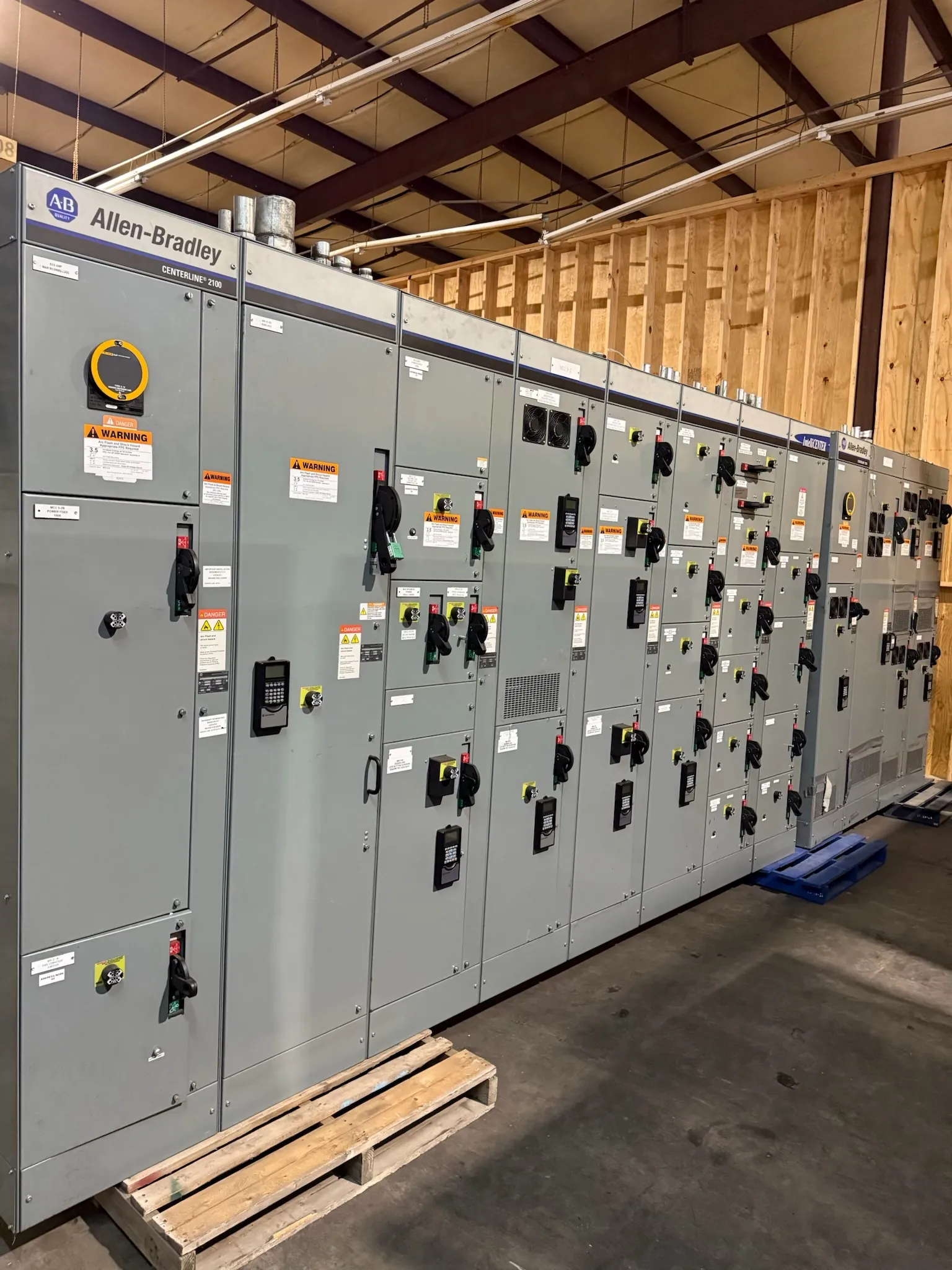
Automatic Transfer Switches for North Las Vegas Projects
An automatic transfer switch (ATS) monitors designated power sources and connects a load to the selected source according to its control settings. In a North Las Vegas facility, the right arrangement depends on the normal and alternate sources, the loads that must transfer, and how the switch will interface with upstream protection and downstream distribution. A project might involve a new distribution lineup, a dedicated transfer-switch enclosure, or integration with other equipment; the appropriate configuration must be established through project-specific engineering.
Specify the source types and system characteristics, intended operating sequence, and loads served before selecting a model. Source sensing can be configured to recognize conditions such as unacceptable voltage or frequency, but thresholds and timing are application decisions—not generic settings. Coordination with the alternate-source controls is essential so the ATS responds as intended without conflicting with generator startup, source availability, or facility requirements.
Transition Methods and Source-Sensing Decisions
Transfer transition describes how the switch moves a load between sources. With an open-transition arrangement, the load is disconnected from one source before connection to the other. Closed-transition equipment can overlap the sources briefly when the system and operating conditions allow it. These approaches have different implications for continuity, source interaction, controls, and protection. The preferred method should be selected with the facility’s electrical engineer and reviewed against the actual sources and loads; it cannot be chosen from the city or product name alone.
Clarify whether transfer is initiated automatically, manually, or by a combination of controls, and whether retransfer to the normal source is automatic or delayed. Identify any required test functions, status contacts, remote indications, or building-management interfaces in the specification. These details affect control wiring and commissioning coordination. A generator-based system also needs a defined relationship between the ATS and generator controls, including what signals are exchanged and how the equipment handles a source that is present but not acceptable.
Load, Withstand, and Protection Coordination
ATS selection requires more than matching a nominal system voltage. The switch’s current rating must suit the connected load and intended duty, while its short-circuit withstand and closing ratings must be evaluated against available fault current and the upstream protective device. These ratings describe equipment capability under specified conditions; they are not substitutes for system voltage, nor do they by themselves establish that an installation is suitable. Rating combinations, protective-device pairings, and applicable listings require confirmation for the specific design.
Provide the engineer with the load schedule, source information, protective-device details, and available fault-current data when known. Explain whether the ATS serves the entire service, a distribution section, or selected critical loads. Load characteristics and planned expansion may influence the rating and arrangement, but adding margin without reviewing the full coordination can affect cost, footprint, and system behavior. The final selection requires qualified engineering review of the site and one-line diagram.
Neutral Switching and Grounding Interfaces — Automatic Transfer Switches in North Las Vegas, NV
Whether the neutral is switched is a system-grounding decision, not a cosmetic product option. The answer depends on the source configuration, how neutral-to-ground bonding is established, and the applicable electrical design. A switched-neutral ATS and a solid-neutral arrangement create different grounding and fault-current paths. Specify the intended grounding scheme and have the engineer verify the transfer equipment’s neutral configuration against the generator, service, and downstream distribution.
Also identify the number and type of poles required, control-power source, auxiliary contacts, enclosure conditions, and any space or access constraints. These interfaces should be resolved before fabrication. Changes to neutral arrangement or control wiring late in the process can affect the equipment layout and coordination with connected assemblies.
UL 1008 and Equipment Documentation — Automatic Transfer Switches in North Las Vegas, NV
UL 1008 is the standard associated with transfer-switch equipment where applicable. It is distinct from standards for switchboards or other distribution products, and it should not be read as a blanket certification of an entire electrical system. Confirm the required listing, product configuration, ratings, and documentation for the specified ATS and installation. Any listing status or project-specific compliance claim must be verified for the actual equipment ordered; it should not be inferred from a general product description.
For a quotation, provide the one-line diagram, source and load details, requested transition method, neutral and grounding requirements, control and indication needs, protective-device information, enclosure location, and applicable project specifications. Include known restrictions on footprint, access, and cable entry. These inputs help the manufacturer identify open design questions early rather than assume details that belong to the project engineer.
North Las Vegas Routing, Clearances, and Delivery Planning
Before fixing lineup dimensions, map incoming and outgoing cable routes, including entry direction, bends, conduit or tray approaches, and transitions to adjacent equipment. Check required working clearances against the actual room or outdoor installation and applicable project requirements. Account for doors, columns, existing services, ventilation, and the space needed to position the assembly. A layout that fits on a drawing may still be difficult to deliver or connect if these conditions are overlooked.
For North Las Vegas delivery planning, confirm the receiving point, access route, unloading arrangements, and any building or site restrictions with the project team. The manufacturer builds new custom power-distribution equipment in the USA using all-American components and ships nationwide; project scope, design review, and confirmed equipment details govern the quotation and schedule. Resolve routing, dimensions, ratings, and interfaces with qualified engineers before release so the ATS arrangement aligns with the facility rather than relying on assumptions.