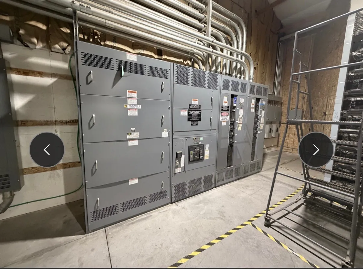
Manufacturing Switchgear for North Las Vegas Facilities
Manufacturing plants depend on electrical distribution that fits the production process, not just the building plan. A custom switchboard or switchgear lineup can be arranged around incoming service, production feeders, motor-control interfaces, and the space available for future circuits. For North Las Vegas projects, early coordination matters: equipment dimensions affect cable paths, electrical-room clearances, delivery access, and the sequence for connecting new distribution to operating equipment.
Our U.S.-built assemblies use all-American components and are manufactured for customers rather than resold. The appropriate equipment type and construction depend on the project’s electrical design, system conditions, and applicable requirements. Ratings, listings, and the suitability of a particular configuration must be confirmed for the equipment and installation; a rating is not the same as a system voltage, and UL 891 applies to applicable low-voltage switchboards—not every type of switchgear or distribution equipment.
Start with the Production Load and Distribution Plan
A useful design conversation begins with what the plant needs to power. Identify major production areas, motors and motor-control equipment, process support systems, and loads that must remain available during planned work. The electrical engineer can then evaluate the incoming source, distribution arrangement, feeder requirements, and protection coordination. Loads with different operating priorities may call for distinct distribution sections or feeder groupings, but those choices need to follow the project’s electrical design rather than a generic lineup template.
Clarify which loads are expected to operate together and whether production changes are anticipated. That information helps the project team consider feeder allocation and practical expansion provisions. Space for future feeders can be valuable, yet unused sections still affect lineup length, room layout, and cable access. Balance future flexibility against the space and interface constraints of the current installation.
Coordinate Motors, Controls, and Equipment Interfaces
Motor loads introduce coordination beyond selecting a feeder. The design team should establish how motors are started and controlled, what protective and control functions are required, and where those functions will be housed. A switchgear or switchboard assembly may distribute power to separate motor-control equipment rather than contain every motor-control function itself. Confirming that boundary early helps avoid gaps in responsibility among the equipment manufacturer, controls integrator, electrical contractor, and engineer.
Document relevant interface requirements, including control-power needs, signal connections, access for conductors, and the relationship between distribution equipment and adjacent control panels. Changes in motor data or control strategy can affect equipment selection and feeder design. The final arrangement should be reviewed against approved drawings and the operating requirements established by qualified project personnel.
Plan Feeder Space, Cable Routes, and Room Clearances
Before fixing lineup dimensions, map incoming and outgoing cable routes. Record where conductors enter and leave, the direction of routing, obstacles, and any constraints imposed by existing ducts, trays, structural members, or adjacent equipment. Cable approach can influence section arrangement and connection locations, so a dimensionally suitable lineup may still be difficult to install if the route has not been checked.
Review working clearances and access against the project design and applicable requirements. Account for doors, nearby panels, columns, equipment that must remain in place, and space needed to bring the assembly into the electrical room. North Las Vegas sites vary in layout and access; do not assume that a standard room or delivery path applies. Field dimensions, site conditions, and handling plans should be verified by the project team before equipment dimensions are finalized.
Shape a Shutdown and Installation Sequence
For an operating manufacturing facility, the connection plan can be as important as the equipment layout. Establish which existing distribution must be interrupted, when affected loads can be unavailable, and what temporary or phased arrangements the project engineer considers appropriate. A planned sequence can influence how the lineup is divided, where connections are made, and whether work is coordinated with other electrical or production changes.
Do not set a shutdown plan from equipment information alone. The facility’s responsible personnel, electrical contractor, and qualified engineer need to review site conditions, system design, and operating constraints. New equipment does not by itself determine whether an existing system can remain in service during installation or how a transition should be carried out.
Prepare a Project-Ready Manufacturing Switchgear Quote
To begin a quotation, provide available one-line diagrams, the specified equipment type and ratings, source information, feeder schedules, motor and control interfaces, and any project requirements for construction or documentation. Include room dimensions, cable-entry directions, route information, required working clearances, delivery access constraints, and the intended installation or shutdown sequence. Identify which details are established and which remain subject to engineering review.
Complete inputs help us assess the proposed assembly and identify questions before drawings and dimensions are fixed. Ratings, applicable listings, component selections, and project-specific interfaces require confirmation; they should not be inferred from a facility’s general voltage description. We manufacture new custom power-distribution equipment in the United States, support short lead times, and ship nationwide, including to North Las Vegas. Actual scope and timing depend on the confirmed project requirements.