Choosing a Transfer Strategy for Nevada Facilities
An automatic transfer switch connects a load to one of two power sources and changes that connection when its control logic detects specified conditions. A Nevada facility may use an electric utility as its normal source and an engine generator as its alternate source, but the one-line diagram and operating sequence determine the actual arrangement. The switch is one part of a wider system that includes sensing, protection, controls and the sources themselves.
New equipment should be selected around the loads that must remain available and the interruptions those loads can tolerate. Life safety circuits, process equipment and building systems may have different restoration requirements and may need separate transfer equipment. A qualified electrical designer should establish the applicable code requirements, source capabilities and project sequence before the equipment is ordered.
Transition Methods and Operating Sequences
Open-transition transfer breaks the connection to one source before making the connection to the other. A delayed-transition arrangement inserts a programmed interval with the load disconnected, which can allow residual motor voltage to decay before reconnection. The acceptable interval depends on the load, motor behavior and operational requirements; it should not be chosen solely to shorten the power interruption.
Closed-transition equipment briefly parallels compatible sources during an approved transfer sequence. It requires appropriate synchronization, source controls and utility agreement, and its use depends on the project rather than on a generic product description. Specify normal-to-alternate transfer, retransfer, exercise and manual operating provisions together. The sequence should also address what happens if a source becomes unacceptable during a transfer or a generator fails to start.
Source Sensing and System Controls
Voltage and frequency sensing determine when a source is considered acceptable. The design should identify sensing locations, adjustable limits and time delays so the system responds to a meaningful outage without unnecessary transfers caused by momentary disturbances. Generator start and stop signals, cooldown, alarms and any building management interface should be defined in the control documents.
Controls need to be coordinated with upstream protective devices and the alternate source. For example, a generator may need time to reach stable operating conditions before the switch transfers load. Where several switches share a generator, the sequence can include staged connection or load shedding if the overall system design requires it. Confirm communication protocols and signal responsibilities at the equipment interfaces.
Also examine the load that will appear on the generator after transfer. Large motor starting currents, electronic power supplies and simultaneous compressor starts can affect generator voltage and frequency. The transfer switch does not correct an undersized source, and a generator's nameplate capacity alone does not describe every transient condition. The project team can evaluate starting sequences and load priorities with the generator supplier, then include any required timing and control signals in the transfer scheme. These details are especially important when several downstream loads restart together after an outage.
Electrical Ratings, Neutral and Protection
Specify system voltage, phase, frequency, continuous current and the load characteristics that apply to the switch. Withstand and closing ratings must be evaluated at the installation point against available fault current and the protective device and clearing conditions permitted for the particular equipment. A rating on its own does not establish a complete coordinated system; the engineer must review the actual source and protection arrangement.
Neutral switching is another project decision. A switched or solid neutral affects how the generator is treated as a separately derived or non-separately derived source and where neutral-to-ground bonding is permitted. The designer must also consider ground-fault sensing and return paths. Apply UL 1008 to transfer equipment where required by the project and authority having jurisdiction, and confirm the specific construction and documentation offered.
Installation and Procurement Details
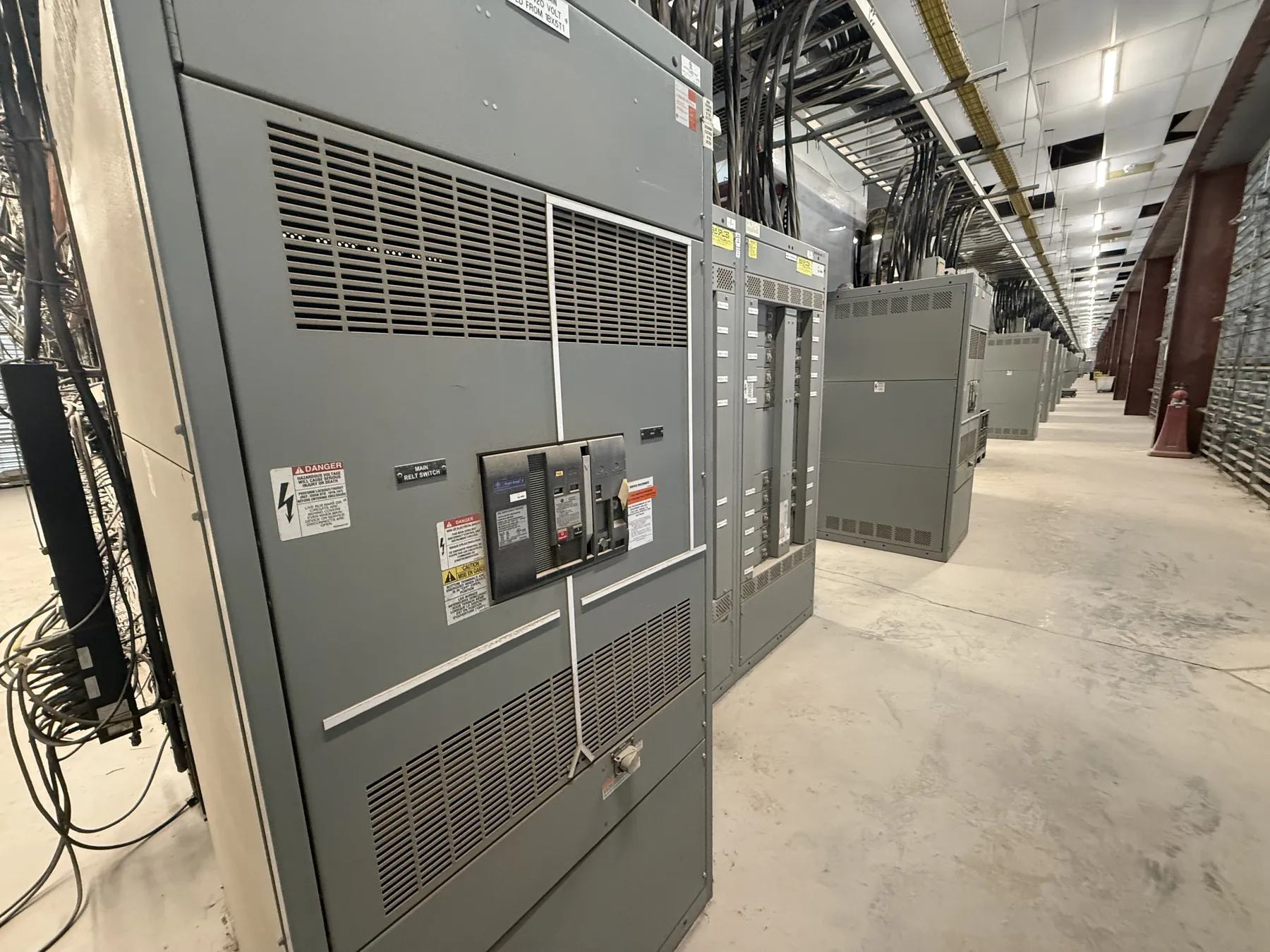
Indoor electrical rooms and outdoor Nevada sites present different enclosure challenges. Define ambient conditions, dust exposure, ventilation, available working space and any outdoor or security requirements rather than assuming one enclosure fits every location. Cable entry, conduit space, terminal sizes and the physical position of the normal and alternate sources should be resolved alongside the equipment layout.
For a U.S.-manufactured switch assembly, provide a one-line diagram, load schedule, sequence of operation and the proposed protective devices with the inquiry. If all-American components are a requirement, identify which components are covered and verify availability and documentation for the selected configuration. Review final submittals, installation instructions and startup responsibilities with qualified personnel before energization.