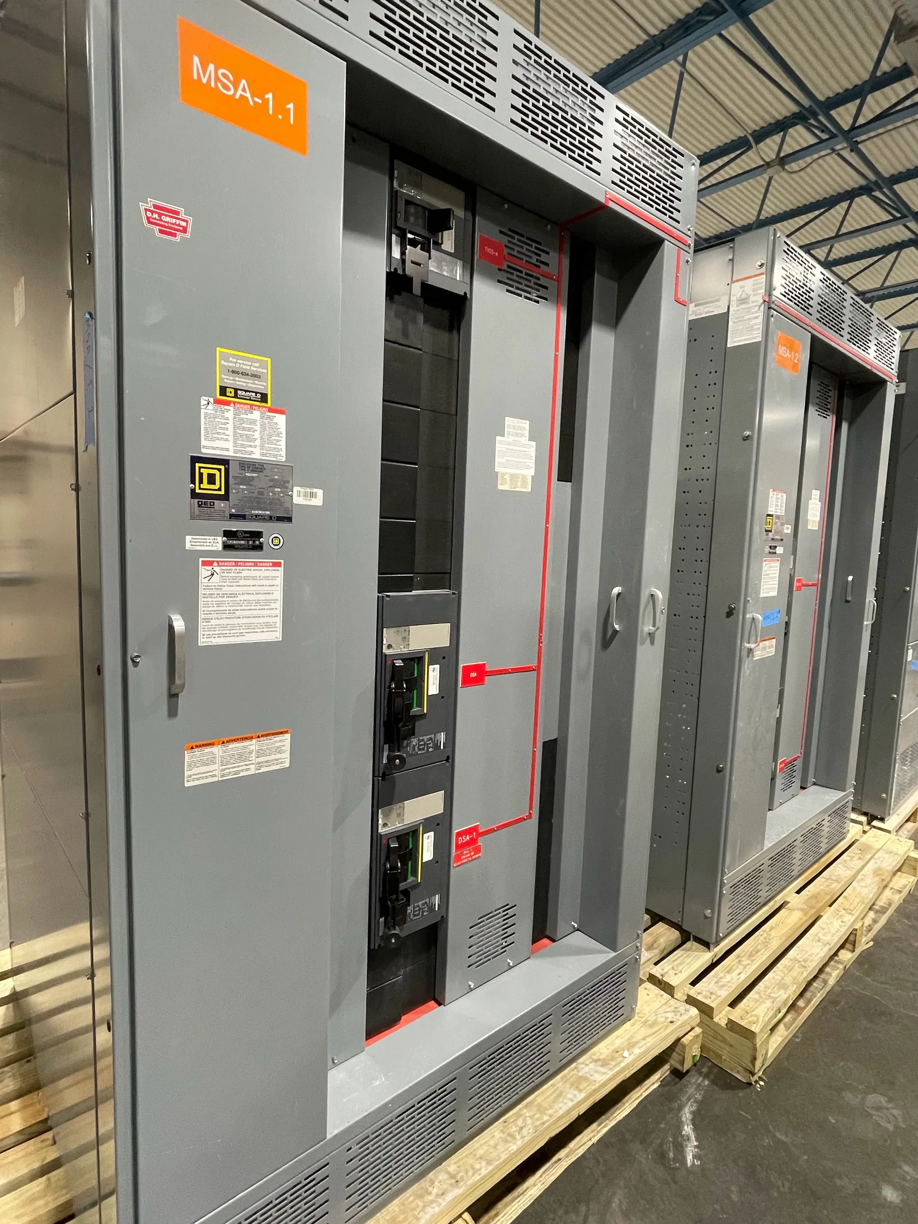
Automatic Transfer Switches for 120/208 V Systems
A 120/208 V automatic transfer switch (ATS) moves selected loads between two power sources, commonly normal utility power and an alternate source such as a generator. The voltage designation alone does not define a complete switch configuration. The system may be three-phase, four-wire, with loads connected phase-to-phase at 208 V and phase-to-neutral at 120 V; the source arrangement and intended load connections must be confirmed for the specific project. A custom ATS should be specified around the actual service, source, and load conditions—not chosen from voltage alone.
Our company manufactures new custom power-distribution equipment in the United States using all-American components. We serve Nevada customers and ship nationwide. Available ATS configurations, ratings, and documentation depend on the equipment design and project requirements, so confirm the specific offering during engineering review and quotation.
Transfer Transition and Source-Sensing Choices — Automatic Transfer Switches for 120/208 V
Transition describes how the switch moves a load from one source to another. An open-transition design disconnects one source before connecting the other, creating a brief interruption. Closed transition momentarily connects sources in parallel and is appropriate only where the sources, controls, protection, and applicable utility conditions support that operation. Delayed transition may introduce a defined interval between disconnection and reconnection when the load or system requires it. These options have different operating and coordination implications; no transition method should be assumed from a 120/208 V designation.
Source-sensing settings also affect transfer behavior. The control scheme may monitor voltage and frequency conditions and use project-defined thresholds and time delays before initiating or completing a transfer. Settings should reflect generator performance, load sensitivity, and the broader protection and control design. For quotation, identify the preferred transition behavior, source types, generator control interface if applicable, and any required alarms or remote status points. Final control details need review by qualified electrical and controls professionals.
Phase Configuration, Neutral, and Load Distribution
Provide the source phase configuration, conductor arrangement, and grounding details for both normal and alternate power. A typical 120/208 V system can serve mixed 120 V and 208 V loads, but the balance and distribution of those loads matter. Uneven phase loading, concentrated single-phase loads, and the way downstream panels are arranged can influence equipment configuration and system performance. Share load schedules or representative load information when available rather than relying on a nominal voltage label.
Neutral switching is a project-specific choice. A solid neutral may be suitable in some arrangements, while a switched neutral may be required or preferred depending on source grounding, separately derived system conditions, and the electrical design. The neutral conductor and grounding scheme must be assessed together; switching decisions cannot be made solely by counting poles or reading the service voltage. State whether the normal and alternate sources have common or separate grounding arrangements and provide the project one-line diagram for review.
Load, Withstand, and Fault-Current Ratings
ATS selection must account for the connected load and the switch’s applicable electrical ratings. The load rating must suit the intended continuous and operational duty, while the equipment’s withstand and closing capability must be appropriate for the available fault current and the protective devices with which the switch is coordinated. These are distinct considerations: a voltage or ampere rating does not by itself establish that the ATS can withstand a site’s prospective fault conditions.
Provide the available fault current at the proposed installation point, the upstream protective-device information, and the relevant bus or assembly rating. Confirm that the ATS and associated equipment are suitable as a coordinated system for the project conditions. Any required rating, short-circuit current rating, or protective-device combination must be verified against the actual equipment documentation and reviewed by qualified engineers. Do not infer suitability from another installation or a similar-looking product.
UL 1008 and Equipment Documentation — Automatic Transfer Switches for 120/208 V
UL 1008 is a standard associated with transfer-switch equipment. Whether it applies to a particular ATS and whether a specific configuration is listed must be confirmed from the documentation for that equipment. A general reference to the standard is not evidence that every switch, control option, rating, or connected assembly is covered. If a project specification calls for a listing or particular evaluation, identify that requirement early so the proposed configuration can be checked against the applicable documentation.
Also distinguish the ATS’s voltage and current ratings from the overall system design and from ratings assigned to related switchboards or other distribution equipment. Confirm the exact configuration, markings, and supporting documents during submittal review; do not assume that a standard, listing, or rating extends beyond its stated scope.
Information Needed to Specify a 120/208 V ATS
A useful quotation package identifies normal and alternate source details, phase and wire configuration, load characteristics, transition preference, neutral requirements, installation environment, and the required controls or monitoring interfaces. Include the one-line diagram, available fault-current information, upstream protective-device data, bus rating, and any project specifications governing listings or documentation. Note facility conditions that may affect enclosure selection or access, such as indoor or outdoor placement and space constraints, without treating those details as substitutes for engineering review.
Our engineering team can review these inputs to establish a proposed custom configuration and identify details that need confirmation. Ratings, listings, and application suitability depend on the actual equipment documentation and project conditions. Qualified electrical professionals must verify the design and coordination for the installation before the equipment is specified for service.