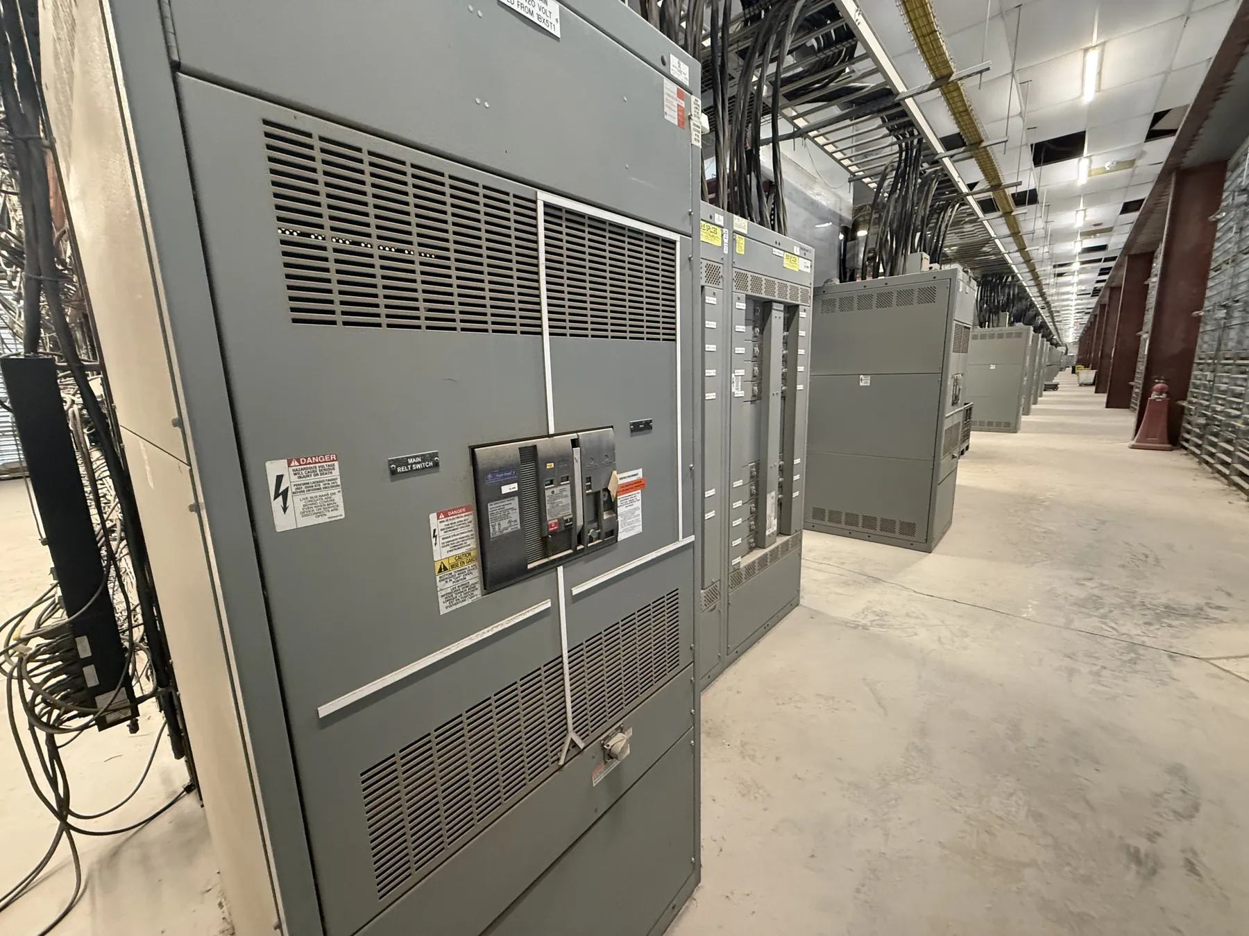
Medium-Voltage Switchgear for Mesquite, Nevada Projects
Medium-voltage switchgear is selected around the electrical system it must serve, not simply the name of a voltage class. For a Mesquite facility, the design team should establish the system’s nominal and maximum operating voltage, grounding method, available fault current, and the way the switchgear connects to the utility or upstream equipment. These details shape the lineup, insulation requirements, protective devices, and interfaces. A manufacturer can build new custom equipment to the approved project requirements, but final selection depends on qualified engineering review of the site and system.
Mesquite’s location in southern Nevada also makes the installation environment relevant. Ambient temperature, solar exposure, enclosure placement, ventilation, elevation, and indoor or outdoor service can affect equipment selection. The design team should compare expected conditions with the selected equipment’s published ratings and specify any required environmental provisions. Local weather assumptions alone are not enough to establish suitability; the actual installation location and equipment documentation must be reviewed.
Define Voltage Class, Fault Duty, and Insulation Level — Medium-Voltage Switchgear in Mesquite, NV
Voltage class identifies the equipment’s intended system range, while the system voltage describes the electrical network where it will operate. Those terms are related but not interchangeable. The project documents should state the system voltage and identify the appropriate equipment class rather than relying on a broad label such as “medium voltage.” Confirm that the specified continuous voltage and insulation level align with the system and applicable design criteria.
Available fault duty is another essential input. It concerns the short-circuit conditions the equipment may be required to withstand or interrupt, depending on the device and its assigned function. The available fault current must be established through the project’s electrical analysis; it cannot be inferred from a facility’s size or location. Specifying equipment without that study can lead to mismatched ratings or unnecessary design constraints. The engineer should also clarify whether future system changes, such as added transformers or generation, affect the fault-duty basis.
Coordinate Switching Devices and Protective Relays
The lineup’s switching and protection scheme should reflect how the facility is supplied and what must be isolated during a fault or planned outage. Breakers, switches, fuses, and other devices have different roles and rating considerations. Their selection depends on the one-line diagram, load characteristics, fault study, and operating requirements—not on a generic equipment configuration.
Protective relays need settings and functions coordinated with upstream and downstream devices. The design should identify the protection objectives, instrument-transformer interfaces, control power, trip and close circuits, alarms, and any communications requirements. Coordination studies help assess whether protective devices respond selectively to the conditions they are intended to detect. Relay model, settings, and logic should be confirmed by the responsible engineer and documented for the project; a quotation or equipment description is not a substitute for that engineering work.
Plan Cable Terminations and Physical Interfaces — Medium-Voltage Switchgear in Mesquite, NV
Cable termination details can affect the enclosure arrangement, compartment dimensions, access space, and installation sequence. Provide the cable type and size, conductor material, number of parallel runs, entry direction, termination method, and any project-specific stress-control or shield-grounding requirements. Also identify whether cables enter from above or below and whether the installation requires rear access or a particular working aisle. These details help the manufacturer develop a practical layout and reduce conflicts with structural, architectural, and electrical plans.
Other interfaces deserve the same attention: bus connections, grounding provisions, control wiring, metering, interlocks, auxiliary contacts, and connections to transformers or other switchgear. Confirm dimensions and connection points against approved drawings before construction and installation. A custom lineup may be configured for the project, but site clearances, cable routing, lifting access, and foundations remain part of coordinated project planning.
Account for Mesquite Heat, Ventilation, and Installation Conditions
For a Mesquite installation, review the expected design ambient temperatures at the equipment location, including whether the gear will sit outdoors, inside a conditioned room, or in a space with limited air movement. Compare those conditions with the selected equipment’s published operating and derating information. Ventilation openings, room cooling, sun exposure, dust management, and enclosure choices may influence the final arrangement. The correct approach depends on the actual room or outdoor pad conditions and the manufacturer’s applicable ratings.
Also consider how the lineup will be delivered to the site and moved into position. Door dimensions, turning space, route limitations, unloading equipment, and the sequence for setting sections can affect shipment configuration. Nationwide shipping from a U.S. manufacturer can support a Nevada project, but transportation planning and site access should be confirmed with the project team rather than assumed.
Prepare a Complete Request for a Custom Quotation
Useful quotation inputs include the one-line diagram, system voltage and grounding, fault-study data, required equipment ratings, relay and metering functions, cable information, indoor or outdoor location, ambient conditions, lineup arrangement, and delivery destination. Include project specifications, preferred manufacturer interfaces where applicable, and the schedule requirements for drawing review and shipment. Clear documents allow the manufacturer to identify open questions before a configuration is finalized.
The manufacturer uses American components and builds equipment in the United States, with short lead times as a stated capability; actual timing depends on the approved scope, component requirements, engineering review, and production planning. Ratings, listings, and project-specific details must be confirmed for the proposed equipment. UL 891 applies to certain low-voltage switchboards and should not be presented as a standard or listing for medium-voltage switchgear. Have qualified electrical engineers review system studies, equipment selection, protection coordination, and site conditions before the design is released.