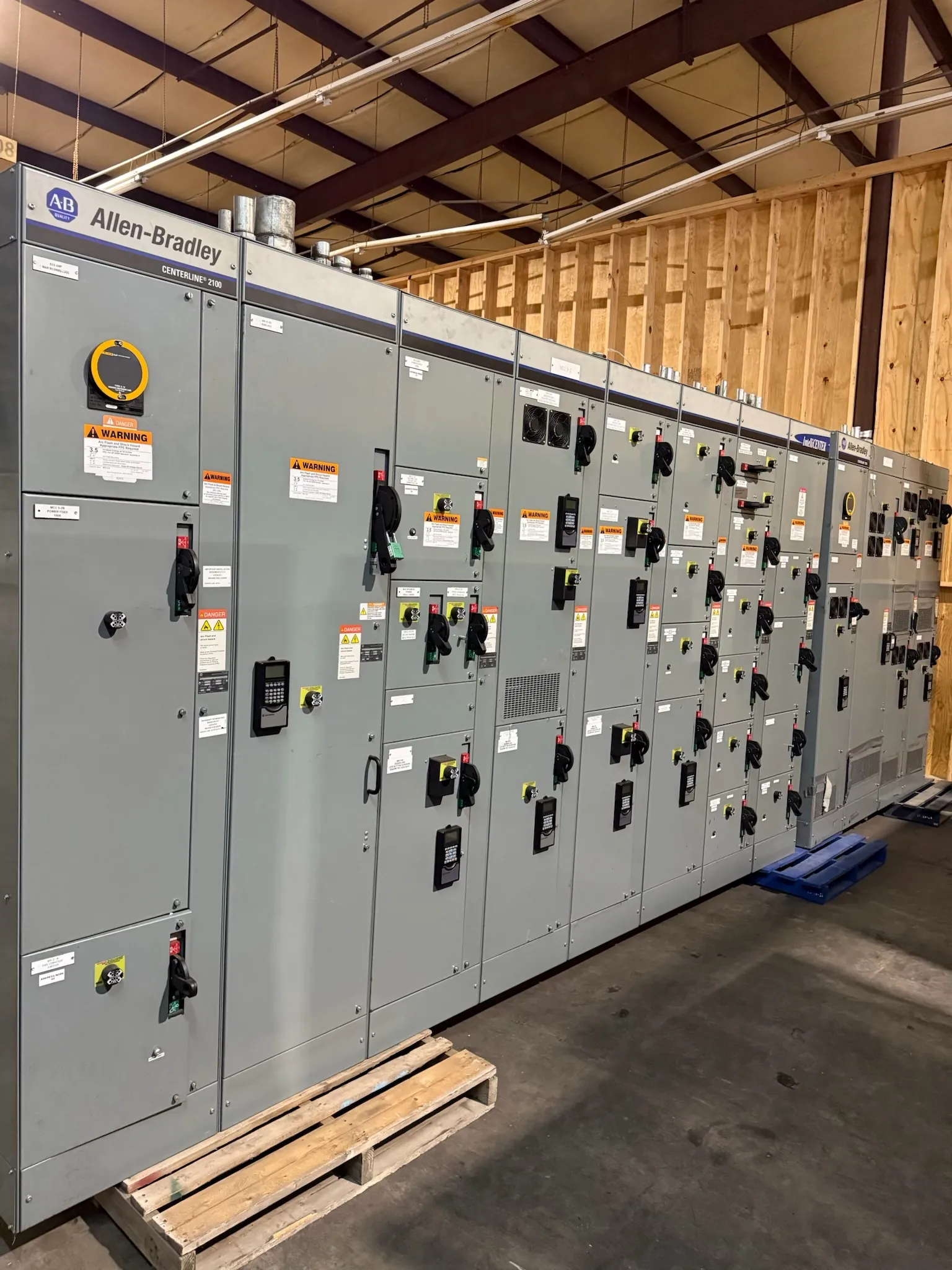
Service Entrance Switchboards for Henderson, NV Projects
A service entrance switchboard establishes the transition between a utility service and a facility’s distribution system. For a Henderson project, its design should begin with the utility metering arrangement, the service disconnect configuration, grounding and bonding requirements, and the available fault current at the proposed equipment location. These details affect how the service section is arranged and what ratings and construction are appropriate; they cannot be settled from the city or building type alone.
Our U.S.-built custom switchboards use all-American components and are manufactured new for customer projects. We ship nationwide, including to Nevada. A useful quotation starts with project documents and confirmed requirements, rather than an assumed standard layout. Lead time depends on the approved scope, component selection, engineering coordination and production requirements.
Confirm the Utility Metering and Service Interface
Before selecting a metering section, establish the serving utility’s requirements for meter location, compartment access, instrument transformers if applicable, service conductors and acceptable equipment configuration. Utility criteria can differ by service type and project circumstances. The electrical engineer and project team should obtain current requirements and coordinate the proposed arrangement with the utility and other authorities having jurisdiction before the switchboard design is finalized.
Also identify the point where utility conductors terminate and where customer equipment begins. Service conductor routing, entry direction, available space, working clearances and the relationship to the main disconnect all influence section dimensions and conductor access. If the design requires provisions for future metering or a particular compartment arrangement, show that in the project documents rather than relying on a general description.
Size the Main Section Around Load and Expansion
Document connected load and the demand assumptions used to determine the service requirement. Include major equipment, operating patterns, known motor or other significant loads, and any planned additions that the facility expects to support. The engineer should review the applicable design criteria and determine the required bus and feeder capacities. A larger nominal system voltage does not by itself establish the switchboard’s current rating, interrupting capability or suitability for the installation.
Expansion planning is a practical tradeoff. Reserving space or capacity for future feeders can make later changes easier, but it may affect the initial lineup, footprint, bus design and protective-device selections. Identify which future loads are firm requirements and which are possibilities. That distinction helps the design team evaluate useful provisions without treating speculative growth as a confirmed load.
Address Fault Current, Disconnects and Coordination
Available fault current at the service equipment is a key input to evaluating its required ratings and protective devices. It must be established for the actual electrical system and service point by qualified project professionals, using current utility information and the system design. Do not infer it from a switchboard’s voltage or ampere rating. The proposed equipment and selected devices must be reviewed against the project’s documented conditions.
Coordinate the main disconnect and downstream protective devices with the distribution design, including the intended protection strategy and any required selective coordination. The engineer should review device characteristics, system configuration and applicable project criteria as a complete system. Requirements can vary with occupancy, use and authority review. Final suitability depends on engineering analysis and site-specific details, not a product description alone.
Grounding, Bonding and Installation Conditions
Service grounding and bonding details belong in the project’s electrical design. Confirm the grounding electrode system, service configuration, bonding locations and any separately derived systems with the responsible engineer. The service equipment arrangement must align with that design and applicable requirements. Specify conductor termination needs and entry locations so the manufacturer can evaluate section layout and access without making assumptions about field conditions.
For a Henderson installation, document the intended indoor or outdoor location, environmental exposure, available electrical-room space, access route and construction constraints. Nevada delivery logistics may require coordination among the site, contractor and receiving team, especially where unloading, staging or installation sequencing is restricted. These conditions should be provided during quotation and engineering review; they do not establish a particular delivery date.
Prepare a Complete Switchboard Quotation Package — Service Entrance Switchboards in Henderson, NV
To support a project-specific proposal, provide the one-line diagram, service characteristics, utility metering criteria, connected-load schedule and demand assumptions, available fault-current information, grounding design, feeder and main-device requirements, and planned expansion. Include equipment location, enclosure needs, cable entry preferences, dimensional constraints, project schedule and any authority comments already received. Flag unresolved items so they can be identified for confirmation instead of silently assumed.
UL 891 applies to relevant low-voltage switchboards when the product and configuration fall within its scope. It should not be read as covering every type of switchgear or every project condition. Ratings, any applicable listing, construction details and acceptance requirements must be confirmed for the specific proposed assembly. Utility acceptance and approvals by authorities having jurisdiction also require project-specific coordination; they should not be presumed from a general product category.