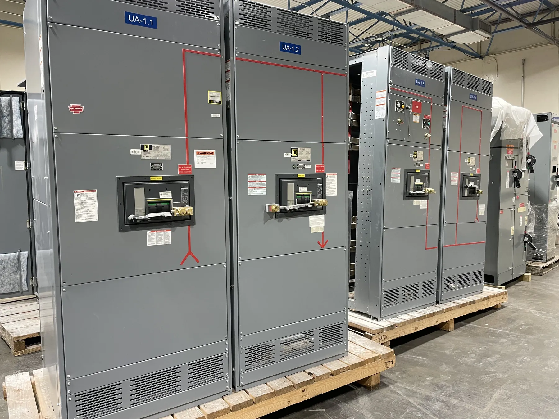
Power Plant Switchgear for Henderson Generation Projects
Generator-connected distribution for a Henderson power plant must reflect how the facility will operate, not just the nameplate rating of a generator. A custom switchgear lineup may need to connect generation to station service, plant loads, a transformer, or a larger distribution system, with each interface affecting the equipment arrangement and protection plan. Begin with the one-line diagram and define normal, startup, shutdown, maintenance, and contingency configurations. Identify which sources can energize each bus in each mode. These details help establish a practical basis for selecting bus and feeder capacity and for coordinating the switchgear with generators, transformers, protective relays, and downstream equipment.
Generator Connections, Synchronizing Interfaces, and Backfeed
Document the generator output characteristics, connection point, grounding approach, and intended switching arrangement before specifying generator breakers or bus connections. Synchronizing functions and controls depend on the overall generating and interconnection design; switchgear provisions must align with the selected relays, control scheme, and equipment supplied by other parties. Backfeed deserves explicit attention. A bus that is normally supplied from one direction may be energized from a generator, another transformer, or a tie under a different operating mode. The project team should identify those paths and define the associated isolation, protection, and interlocking requirements. The manufacturer can build to an approved design, but qualified power-system engineers must establish and validate the protection and control scheme.
Size Bus and Feeders Around Load and Expansion Plans
For a useful equipment quotation, provide connected loads as well as demand assumptions, load characteristics, and expected operating combinations. Separate continuous plant auxiliaries from intermittent or starting loads where the design team has that information. Include large motors, pumps, compressors, cooling equipment, and other loads that may influence feeder selection or voltage performance. A list of equipment without operating context can lead to an incomplete capacity basis. Document planned expansion too: future generators, additional process loads, or reserved feeder positions can affect lineup length, bus selection, and connection provisions. Avoid choosing capacity from a single aggregate figure without review of how loads are expected to run together and what the system must support during abnormal conditions.
Account for Auxiliary Loads and Changing Operating Modes
Plant auxiliary distribution may serve essential systems, general services, and equipment required during startup or shutdown. Determine which loads must remain available when a generator is offline, when utility supply is unavailable, or when a bus section is isolated for planned work. Transfer arrangements and bus ties can improve operating flexibility, but they also introduce additional switching states and protection-coordination questions. The design should make source relationships and intended configurations clear to operators and maintenance teams, while avoiding assumptions that a tie will always be closed or that every source can operate in parallel. Provide the anticipated operating modes and the responsibility boundaries for controls, relays, and switchgear interfaces during design review.
Coordinate Ratings, Protection, and Equipment Scope
Specify system voltage, continuous current requirements, available fault-current information, and the protective devices or relay functions required by the approved study. These are related but distinct design inputs: a voltage designation does not establish bus rating or interrupting capability, and equipment ratings must be confirmed against actual project conditions. Coordination may involve generator protection, transformer protection, feeder devices, utility interconnection requirements, and downstream equipment. Applicable product standards depend on equipment type and scope; UL 891 applies to applicable low-voltage switchboards, not every switchgear assembly or voltage class. Confirm the requested listing, ratings, and construction details for the specific configuration rather than assuming a standard applies across the entire plant.
Prepare Henderson Project Information for a Buildable Quote
Useful quotation documents include the latest one-line diagram, equipment schedule, site voltage and fault-current data, generator and transformer information, feeder destinations, load and demand assumptions, protection requirements, and the planned expansion basis. Note room dimensions, access routes, indoor or outdoor placement, environmental conditions, and any limits on lineup sections or cable entry. Henderson-area site conditions can vary by facility, so heat, dust, ventilation, and installation logistics should be evaluated for the actual location rather than assumed. Clear interface schedules also help distinguish switchgear scope from generator, controls, and field-installation work. New custom equipment is manufactured in the United States using all-American components and can ship nationwide; lead time depends on finalized design, components, and project requirements.