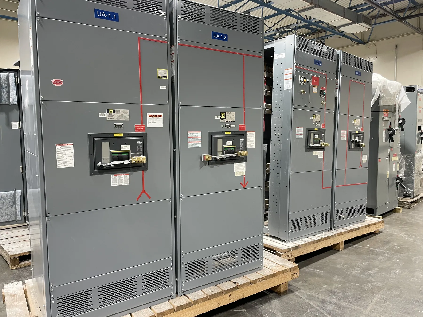
Medium-Voltage Switchgear for Gardnerville Projects
Specifying medium-voltage switchgear for a Gardnerville facility starts with the electrical system it must serve, not with a product label alone. The project team needs to establish the system voltage class and the equipment’s required ratings, then match the assembly to the source, connected loads, protection scheme and site conditions. Those decisions affect the switchgear lineup, control interfaces, cable connections and installation requirements. Our U.S.-manufactured equipment is built with all-American components and can ship nationwide, including to Nevada. Project-specific ratings, configurations and lead times must be confirmed during engineering and quotation.
Define Voltage Class, Fault Duty and Insulation Level — Medium-Voltage Switchgear in Gardnerville, NV
System voltage and equipment ratings are related, but they are not interchangeable. The one-line diagram and utility or facility design documents should identify the nominal system voltage, grounding arrangement and operating conditions so the engineer can select compatible equipment. Available fault current at the switchgear location is another essential input. The assembly’s interrupting and withstand capabilities must be evaluated against the calculated fault duty and the protective devices’ performance; assumptions based only on upstream equipment or a general voltage description can lead to an unsuitable specification.
Insulation level is a separate design consideration. It describes the equipment’s insulation withstand requirements and must be appropriate for the system and installation conditions. The project engineer should confirm the applicable ratings and insulation requirements together, rather than infer one from the other. Medium-voltage switchgear is not covered by UL 891, which applies to applicable low-voltage switchboards. Any requested listing, standard or compliance requirement should be identified for the specific equipment and verified as part of project review.
Choose Protection Relays Around the System
Protective relays should reflect the power system’s protection and coordination study, not a generic feature package. The specification should identify the functions required, the signals available from instrument transformers and the intended trip and alarm interfaces. It should also describe how the switchgear relates to upstream protection, downstream devices, generators or other sources where applicable. Relay settings and coordination require qualified engineering review using project-specific system data; they cannot be determined from the city or equipment type alone.
Controls and communications deserve the same attention. Identify required status points, remote indications, control power and any connection to a facility monitoring system. The team should clarify which interfaces are part of the switchgear scope and which are provided by others. This helps prevent a lineup from being technically suitable but difficult to integrate with the site’s protection, controls or operating practices.
Plan Cable Terminations and Physical Interfaces — Medium-Voltage Switchgear in Gardnerville, NV
Cable entry and termination details influence the lineup’s layout and installation. Provide the cable type and sizes, number of conductors per phase where applicable, termination approach, entry direction and available space for bending and connection. The design team should also confirm whether connections are incoming, outgoing or arranged for a particular bus or transformer interface. These details need to be reconciled with the switchgear drawings and the cable contractor’s installation plan.
Equipment arrangement, access clearances and room dimensions should be checked against the actual building or enclosure. Note doors, walls, structural obstructions, cable trenches and routes for bringing equipment to its final position. For outdoor placement, specify the enclosure and environmental requirements rather than assuming that an indoor configuration can be used outside. Project drawings should resolve equipment orientation and interfaces before fabrication proceeds.
Account for Gardnerville Elevation and Site Conditions
For a Gardnerville installation, include the site elevation in the equipment review. Elevation can affect how applicable electrical ratings are evaluated, so the design team should confirm any required adjustments for the actual location and selected equipment. Also identify whether the switchgear will be indoors or outdoors and document the surrounding environmental conditions, including expected temperature range, moisture exposure, dust and other relevant site factors. These inputs help determine suitable construction and any project-specific provisions.
Nevada shipping logistics should be coordinated with the site’s access and receiving conditions. Confirm the delivery destination, unloading arrangements, route into the electrical room or equipment area, and any scheduling constraints. This is especially useful when the final location has restricted access or when the assembly must pass through an existing building. Shipping nationwide is available, but transit and delivery details depend on the order and destination.
Prepare a Complete Project Specification
A clear request for quotation should include the latest one-line diagram, nominal system voltage, calculated available fault duty, grounding information, required insulation level, relay and control requirements, cable termination data, indoor or outdoor placement, site elevation and environmental specifications. Add lineup dimensions, interface drawings, applicable project standards and requested documentation. Identify open engineering questions rather than treating preliminary values as final ratings. With these inputs, the manufacturer and qualified project engineers can review the required configuration, clarify scope boundaries and confirm equipment details before an order is released.