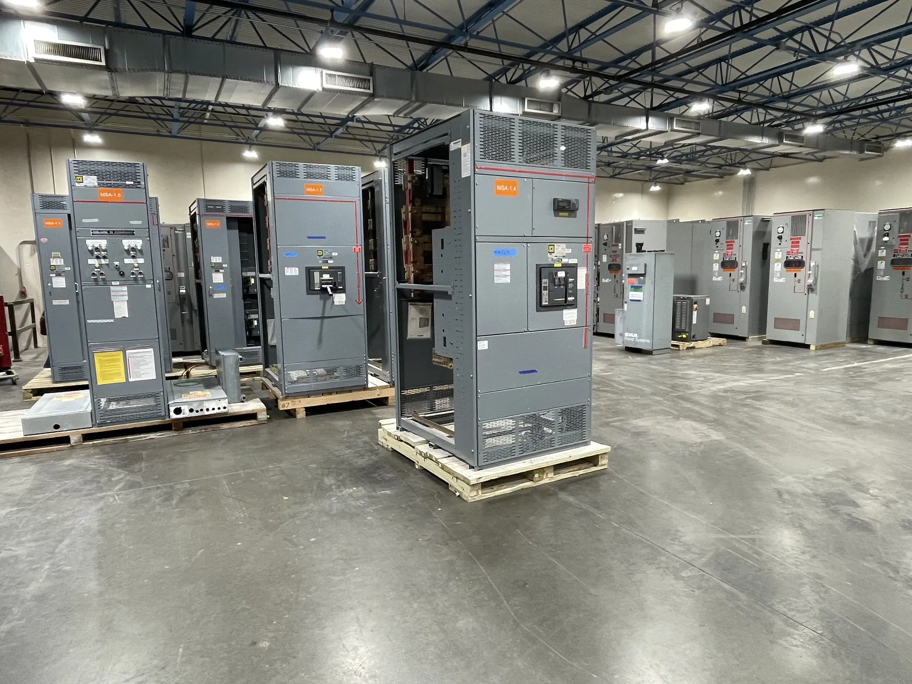
Planning Service Entrance Switchboards for Fernley Projects
A service entrance switchboard brings a facility’s incoming electrical service to its main disconnect and distributes power to downstream equipment. For a Fernley project, the design depends on more than the switchboard’s nominal voltage or ampere rating. Utility metering requirements, the available fault current, service grounding, installation conditions and the authority having jurisdiction all affect how the service section must be configured. Establishing these details early helps align the manufactured equipment with the project’s electrical design and approval process.
Our U.S. manufacturing team builds new custom service entrance switchboards using all-American components and ships equipment nationwide, including to Nevada. A quotation can begin with the project’s one-line diagram, load information, service requirements and equipment layout. Final ratings, construction details, applicable listings and approval requirements need confirmation against the project documents and site conditions by qualified electrical professionals.
Resolve Metering and Utility Interfaces Before Layout
Utility metering can shape the service section’s arrangement, compartments and access requirements. Confirm whether the utility requires a particular metering configuration, instrument provisions, compartment access or other service interface. Those requirements can vary by utility and project, so a general product description is not a substitute for written project-specific criteria.
Identify the incoming source and the intended point of connection, then coordinate the switchboard design with the utility’s service requirements and the electrical engineer’s drawings. Clarify which party furnishes or installs metering components and how the utility expects the equipment to be reviewed. Resolving these interfaces before finalizing dimensions can reduce redesign and help keep utility review aligned with the equipment submittal.
Coordinate the Main Disconnect and Service Grounding
The main disconnect arrangement should reflect the project’s service configuration, distribution plan and operating requirements. Useful quotation inputs include the planned main-device type, service rating, downstream feeder arrangement and any required provisions for future circuits. The rating of a device is not the same as the system voltage; both must be specified and checked for compatibility with the project design.
Service grounding and bonding details also require deliberate coordination. The electrical engineer should define the applicable grounding arrangement and how it interfaces with the service conductors, switchboard and facility grounding system. The manufacturer can build to documented requirements, but grounding decisions must be established by qualified professionals under the applicable project criteria and reviewed by the authority having jurisdiction.
Verify Available Fault Current and Equipment Ratings
Available fault current at the service entrance is a key input when selecting and coordinating equipment. Obtain the utility’s or engineer’s project-specific value and identify the assumptions behind it. Switchboard short-circuit ratings and protective-device ratings must be evaluated against the available fault current and the complete system design; a voltage or ampere rating alone does not establish suitability.
Coordinate protective devices and downstream equipment as part of the electrical study and design review. Do not assume a rating based on a typical installation or a nearby facility. If the source, transformer or service arrangement changes, the fault-current information and equipment coordination may need to be revisited. The final design and ratings require review by qualified engineers and applicable approval authorities.
Account for Fernley Site Conditions and Future Feeders
Installation location affects practical choices such as enclosure arrangement, cable entry, working clearances, routing and the path from the service point to downstream distribution. For a Fernley site, provide the actual installation location and relevant facility conditions rather than relying on a city-level assumption. Indoor or outdoor placement, environmental exposure, available space and access for installation can all influence the specified construction.
Consider whether spare feeder provisions are needed for planned expansion or operational changes. Identify the intended feeder sizes and destinations where known, and distinguish usable spare provisions from spaces reserved for future work. Adding capacity or provisions has design, layout and rating implications, so these needs should be documented rather than treated as interchangeable options.
Prepare a Clear Quotation and Approval Package
For a useful quotation, provide the latest one-line diagram, service and system voltage, required switchboard ratings, metering criteria, available fault-current information, grounding requirements, feeder schedule, installation environment and approximate equipment dimensions or layout constraints. Include the project’s approval path and any documented utility criteria. If details remain unresolved, identify them as open items so they can be confirmed before the design is finalized.
Our team manufactures new custom power-distribution equipment in the United States and supports short lead times, with timing dependent on confirmed scope and project requirements. Applicable listings must be confirmed for the specific equipment; UL 891 applies to certain low-voltage switchboards, not every switchgear product or voltage class. Submittals, ratings, utility interfaces and authority approvals should be coordinated before release for manufacture and installation in Fernley.