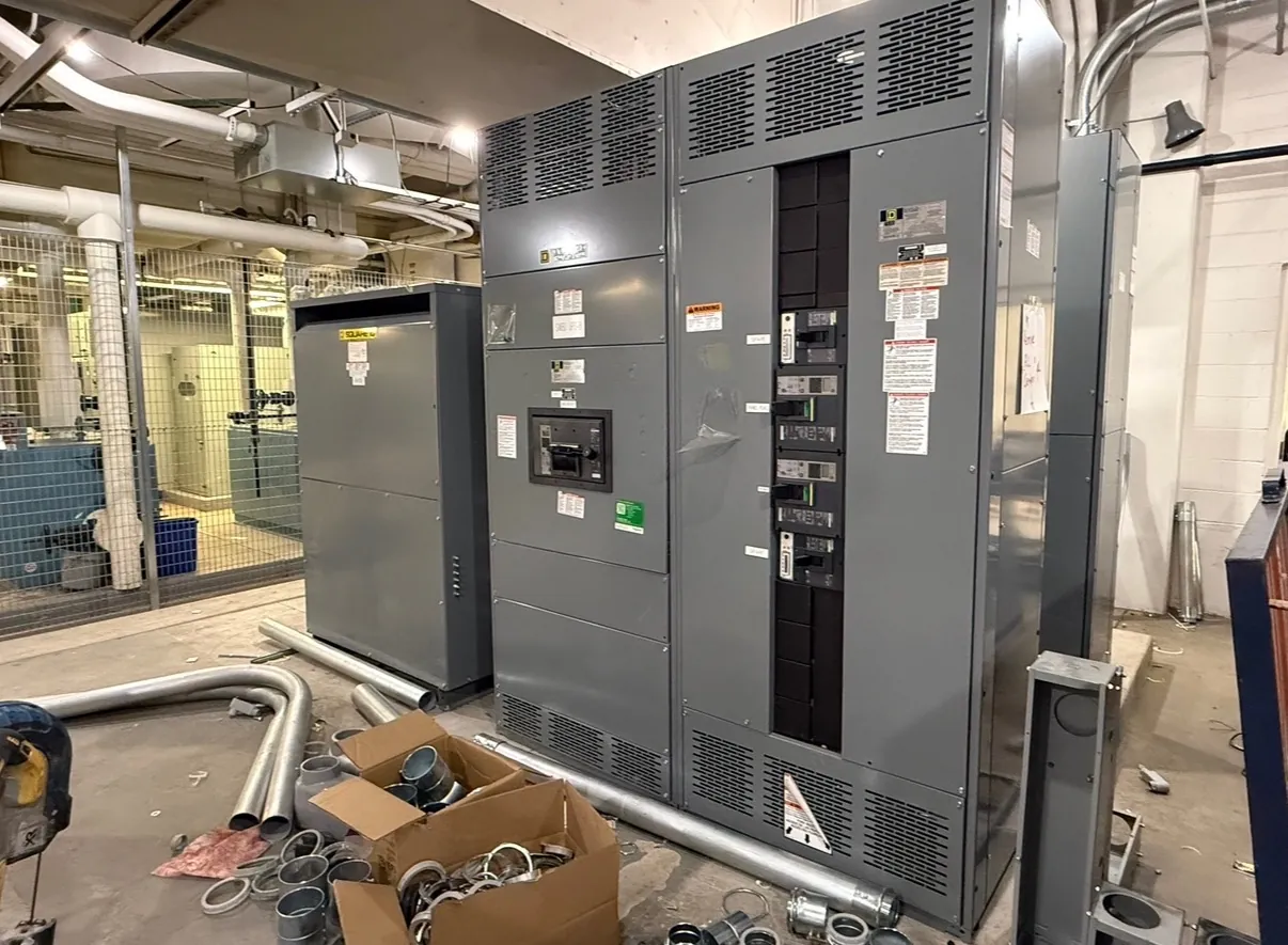
Medium-Voltage Switchgear for Fernley, NV Projects
Medium-voltage switchgear connects, protects and isolates portions of an electrical distribution system above the low-voltage range. For a Fernley facility, selecting an assembly starts with the electrical design and the conditions at its point of connection—not with a product label alone. The required system voltage class, available fault duty, insulation level, switching arrangement and protective scheme must be established for the project. Those values are related but not interchangeable: a switchgear voltage class is not the same thing as a system’s operating voltage, and a fault-duty rating is not a substitute for either.
We manufacture new custom power-distribution equipment in the United States using all-American components and ship nationwide, including to Nevada. Project-specific medium-voltage requirements should be reviewed by qualified electrical engineers alongside source information, one-line diagrams and site conditions. The final configuration depends on the application and applicable requirements; no rating or listing should be assumed from a general product description.
Define Voltage Class, Fault Duty and Insulation Level — Medium-Voltage Switchgear in Fernley, NV
The switchgear’s voltage class must suit the system and the equipment connected to it. Engineering review should confirm the nominal system voltage, grounding arrangement and relevant maximum operating conditions, then select equipment with an appropriate rating. A separate review establishes the available fault current and the switchgear’s required short-circuit withstand and interruption capabilities, as applicable to the proposed design. Utility or upstream-source information may be needed to make that assessment.
Insulation level is another distinct design input. It addresses the equipment’s ability to withstand specified electrical stresses; it should be coordinated with the system voltage and project requirements, not inferred from the voltage-class name. These decisions affect equipment selection, clearances, terminations and interfaces with connected cables. UL 891 applies to applicable low-voltage switchboards; it should not be treated as the governing standard or a certification claim for medium-voltage switchgear. Applicable standards, listings and ratings require confirmation for the actual assembly and project.
Choose the Switching Arrangement Around the Source
Fernley project teams should describe how the electrical source is expected to perform and what continuity needs the facility has. Is there one incoming source or more than one? Does the design call for sectionalizing, a tie between sections, or a specific arrangement for isolating equipment? How should the system respond to a source interruption or planned maintenance? These questions help engineers evaluate the lineup arrangement and operating functions without assuming that a particular topology suits every site.
Reliability goals also need to be balanced against complexity, space and coordination. Additional switching points or alternate-source provisions may support a project’s continuity objectives, but they introduce interfaces and protection decisions that must be engineered as a system. Spare feeder requirements should be stated early: identify whether future capacity means reserved physical space, a provision for later equipment, or a fully equipped feeder position. The appropriate choice depends on the expansion plan and the design basis.
Coordinate Relays, Cables and Field Interfaces
Protective relays detect defined electrical conditions and initiate a protective response through the specified equipment. Relay functions and settings depend on the source, connected loads, grounding, fault study and coordination with upstream and downstream devices. Provide available relay requirements, control power expectations, communications needs and interface details when known. Qualified engineers must determine protection settings and verify coordination; they cannot be selected reliably from a general description of the facility.
Cable terminations deserve equal attention. The design team should confirm cable type, conductor details, termination approach, entry direction and the space and access required at the installation. These inputs influence compartment layout and the connection between field cables and switchgear. Clarify whether control and communications wiring must interface with other equipment, and identify any project-specific requirements for metering, alarms or remote signals. Final terminations and interfaces require review against the selected equipment and field conditions.
Plan for Fernley Installation Conditions
Shipping equipment to Fernley is a logistics consideration, not evidence of a local factory or office. Before specifying a lineup, confirm the destination, receiving access, unloading arrangements, route into the building and available installation space. Site review should account for the intended indoor or outdoor location, environmental exposure, room dimensions, working clearances and the path for incoming and outgoing cables. Actual site conditions may affect the enclosure, layout and installation plan, so provide drawings or measurements rather than relying on assumptions.
Construction sequencing matters as well. The project team should establish when the electrical room or equipment pad will be ready, how the assembly will be moved into position, and which trades are responsible for cable, control and grounding interfaces. These details help align manufacturing documentation and delivery planning with the installation schedule. Lead time depends on the confirmed scope, design approvals and production requirements; a project schedule should be discussed during quotation rather than presumed.
Information That Supports a Useful Quotation — Medium-Voltage Switchgear in Fernley, NV
A quotation can be more specific when the request includes the one-line diagram, system voltage and grounding information, available fault-current data, required ratings, source arrangement, feeder schedule and known relay functions. Include cable and termination details, indoor or outdoor location, space constraints, environmental conditions, spare feeder expectations, control interfaces and the desired delivery destination in Fernley. Identify which items are established and which remain subject to engineering review.
We use the project scope to develop a custom new-equipment proposal, with ratings and configuration subject to confirmation. Reviewing the electrical design, applicable standards, site conditions and interfaces with qualified project engineers helps ensure the proposed medium-voltage switchgear addresses the actual distribution system rather than a generic specification.