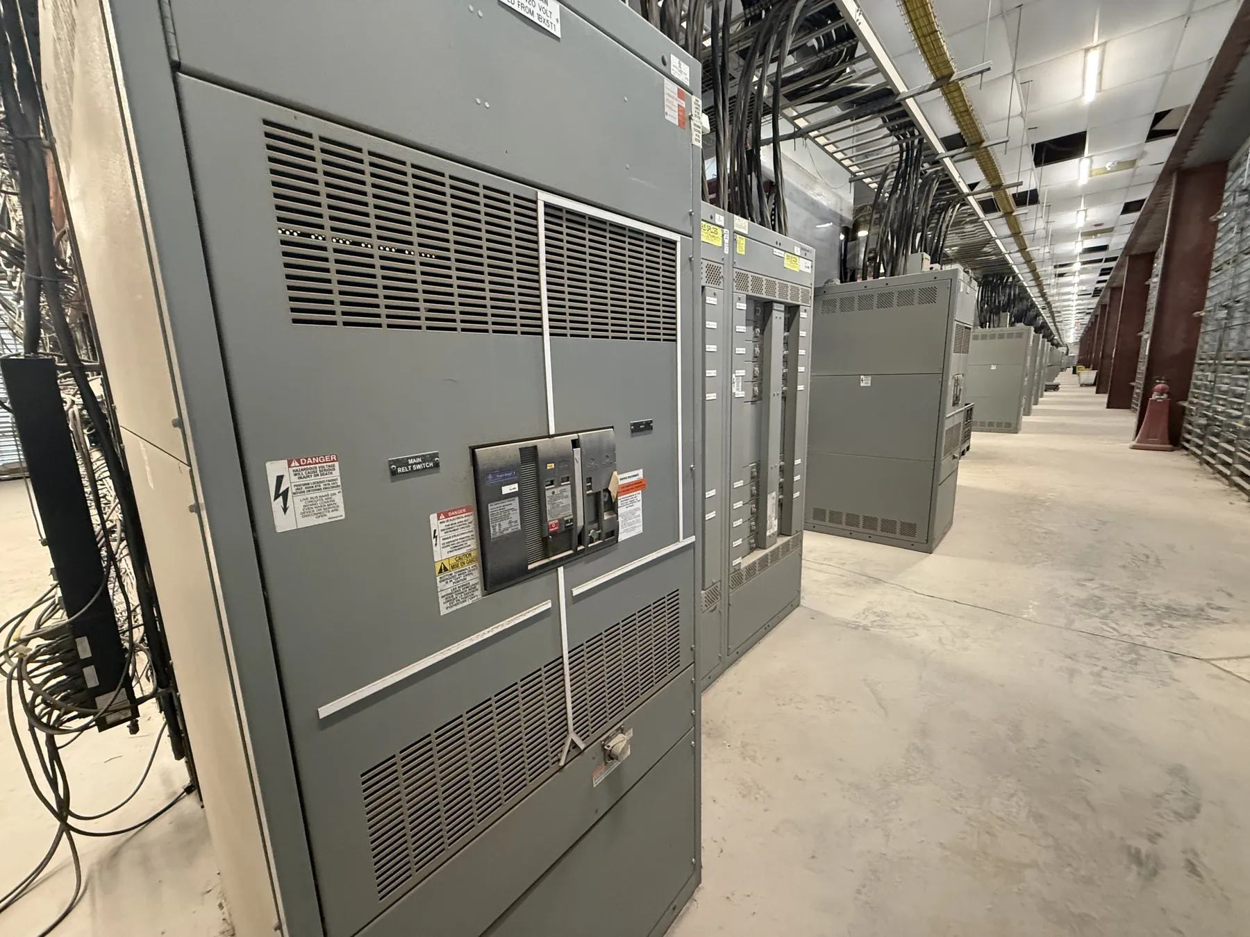
Low-Voltage Switchboards for Fernley, NV Projects
Fernley facilities may need a low-voltage switchboard to receive power from a utility service or other source and distribute it to building loads and downstream panels. The right arrangement depends on the electrical design, the source and service configuration, the loads being served, and the requirements for maintenance and future changes. We manufacture new custom power-distribution equipment in the United States using all-American components, and ship nationwide, including to Nevada. Project-specific engineering and documentation are necessary to determine whether a proposed switchboard fits a particular Fernley installation.
Service and Feeder Arrangements — Low-Voltage Switchboards in Fernley, NV
At the service end, the design team must identify the incoming conductors, service disconnecting means, metering interface where applicable, and any source-side requirements. The switchboard’s distribution section can then be arranged around outgoing feeders for equipment, panels, or other portions of the facility. Feeder quantity, ampacity, termination provisions, and physical routing affect the lineup’s configuration and space requirements.
Clarify whether the board serves as service equipment or is installed downstream of another disconnecting means. That distinction can affect the required equipment arrangement and project documentation. Also identify any generator, transformer, transfer equipment, or alternate-source interface that is part of the overall system. The switchboard should not be assumed to provide transfer or source-control functions unless they are specifically included in the engineered scope.
Bus Sizing and Available Fault Current — Low-Voltage Switchboards in Fernley, NV
Bus selection must account for the electrical system and the load design, not just a headline ampere rating. The engineer needs to establish the required bus rating, neutral and grounding provisions, and any applicable temperature or installation conditions. A switchboard’s rating is not the same thing as the system voltage; both must be specified and confirmed for the project.
Available fault current at the equipment location is also a key design input. It depends on the source and upstream system characteristics, so it should be provided or verified by the responsible electrical engineer rather than estimated from the switchboard’s nominal rating. The equipment’s short-circuit and protective-device coordination requirements must be evaluated against the actual system. Changes to a transformer, upstream protection, or source arrangement may change the available fault current and require review of the equipment selection and documentation.
Source Reliability, Spare Feeders, and Future Loads
For a Fernley project, describe the consequences of a power interruption and the intended role of each source. Reliability needs may influence the broader system design, such as whether the facility has an alternate source or requires particular separation and coordination of distribution sections. A switchboard alone does not establish continuity of power; source equipment, controls, protective devices, and operating requirements must be considered together by qualified project professionals.
List both immediate feeder requirements and planned spare positions. A spare feeder can provide a defined path for a future load, but its provisions must be specified rather than assumed. Consider expected load characteristics, feeder termination space, cable entry and routing, and whether future work must remain compatible with the original lineup. Adding capacity later may require physical access and a system review, so the project team should identify expansion goals early.
Installation Location and Fernley Site Conditions
Identify whether the switchboard will be installed indoors or outdoors, the available room or enclosure space, and the planned access for installation and maintenance. Room layout, working clearances, door and equipment access, cable entry direction, and the route from the delivery point to the final location can affect the lineup design and shipping plan. Site conditions such as exposure to dust, moisture, temperature variation, or other environmental factors should be documented so the design team can evaluate suitable construction.
For delivery to Fernley, confirm the receiving location, unloading arrangements, access restrictions, and any schedule or staging constraints with the project team. These logistics do not replace field verification: dimensions, mounting conditions, conductor routes, and interfaces with adjacent equipment should be checked against current site information before finalizing the design.
UL 891 Scope and Project Documentation — Low-Voltage Switchboards in Fernley, NV
UL 891 applies to low-voltage switchboards within its applicable scope; it should not be treated as a blanket standard for every electrical assembly or as confirmation of a particular project’s compliance. Listing status and the documentation available for a proposed configuration must be confirmed for the specific equipment. Do not infer a listing from a product description or from an individual component rating.
For a quotation, provide the one-line diagram, system voltage, required ampere and fault-current information, source and service arrangement, feeder schedule, protection and coordination requirements, installation conditions, and any requested listing or documentation criteria. Include spare feeder needs, equipment interfaces, dimensions, cable entry preferences, and delivery-site constraints. Qualified engineers must review the electrical design and site conditions; ratings, listing documentation, and final configuration require project-specific confirmation.