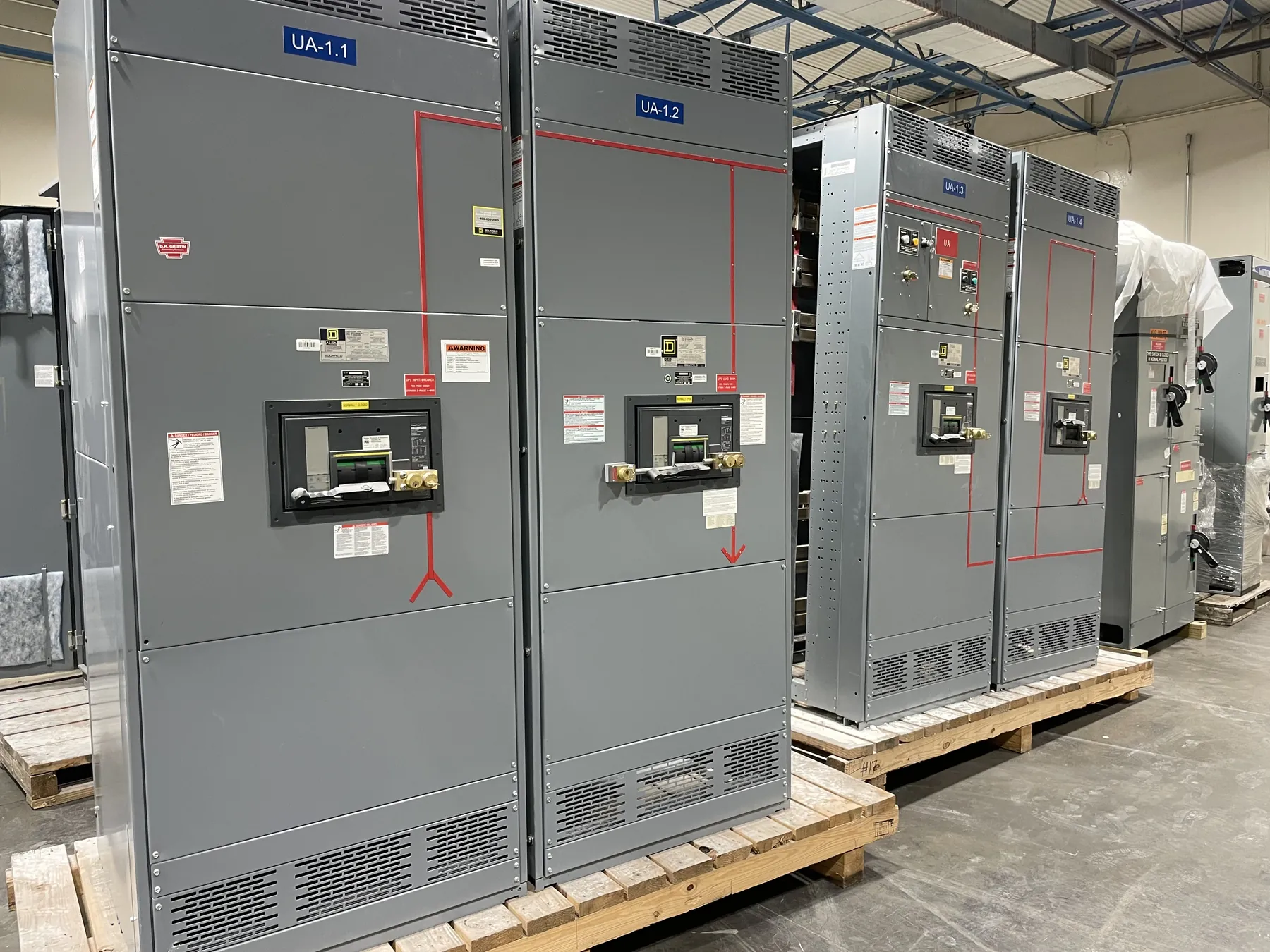
Organize Power With a Low-Voltage Switchboard
A low-voltage switchboard brings incoming power and outgoing feeder protection together in an assembly suited to the project's distribution plan. A new lineup may serve as service equipment or receive power from another distribution source. The one-line diagram should show the system voltage, phases, neutral, grounding arrangement, incoming connections and the loads supplied by each feeder.
For a Nevada project, a U.S. manufacturer needs more than a total load figure to develop the layout. The number and type of source and feeder devices, metering, available installation space and cable entry locations all influence the construction. A qualified electrical engineer should establish the system requirements and review the proposed design.
Define the Service and Feeder Arrangement
If the switchboard is service equipment, establish the utility's service characteristics and metering requirements before finalizing the incoming section. The design may need a main disconnect, utility metering space and provisions for service grounding and bonding. The engineer and installer should confirm the applicable code and utility requirements for the actual service rather than treating every incoming section as a service entrance.
For outgoing circuits, identify feeder quantities, loads, protective-device types, cable sizes and termination arrangements. Indicate whether spare devices or space for future feeders are needed and whether those provisions must be usable without major modifications. Labeling, metering and separation requirements should be coordinated with the equipment's layout and the facility's operating plan.
Size Bus and Connections for the Load
Main bus and feeder ratings depend on calculated loads, the intended operating duty and the complete assembly design. Provide connected loads, demand assumptions and foreseeable expansion so the engineer can establish required continuous current. Ambient temperature, enclosure ventilation and equipment arrangement can affect the manufacturer's rating criteria. A larger individual conductor does not by itself establish a higher rating for the finished switchboard.
Specify copper or aluminum when the project requires a particular bus material, and identify neutral and equipment grounding conductor needs separately. The neutral design should reflect the system and connected loads. For multiple cable sets or a busway connection, confirm terminal capacity, conductor entry and bending space. Coordinate field-made joints and tightening instructions with the installation contractor.
Match Fault Duty and Protective Devices
Obtain the available short-circuit current at the switchboard location for the relevant source configurations. The proposed assembly's short-circuit current rating and each protective device's interrupting rating must be suitable for the application. A device rating is not automatically the rating of the complete lineup, and an upstream protective device should not be credited without support for the specific combination.
The project engineer should evaluate protective-device settings and coordination with upstream and downstream equipment. Where a series-rated combination is proposed, verify its documented applicability and code suitability rather than selecting devices independently. Updates to source capacity or added generation may change the fault study and require another review before the equipment design is released.
Verify UL 891 and Project Documentation
UL 891 addresses applicable low-voltage switchboards. A specification can require equipment evaluated and listed to that standard, but the reference alone does not prove that a particular assembly is listed. Request the listing information, identification and scope for the proposed configuration, including any restrictions on devices or field modifications. Confirm acceptance requirements with the authority having jurisdiction.
Ask for drawings and documentation showing the system and assembly ratings, device schedule, enclosure, connection points and applicable inspection or test scope. The responsible engineer should compare the submittal with the one-line and project specifications. For other product types or voltage classes, identify their own applicable standards rather than extending UL 891 beyond low-voltage switchboards.
Coordinate Manufacturing, Site Access and Handoff
Before manufacturing, confirm enclosure conditions, working clearances, shipping splits and the dimensions of the path to the final equipment location. A Nevada installation may be indoors or outdoors, so specify the actual ambient conditions and environmental exposure. The project team should verify enclosure selection, access and ventilation against the documented site requirements and applicable codes.
When all-American components are required, state the origin criteria and ask for appropriate supporting information; U.S. assembly alone does not establish the origin of every part. Coordinate receiving, unloading and field connections with the installer. Supply final drawings, installation instructions and agreed factory test records for qualified personnel to use during inspection, commissioning and energization.