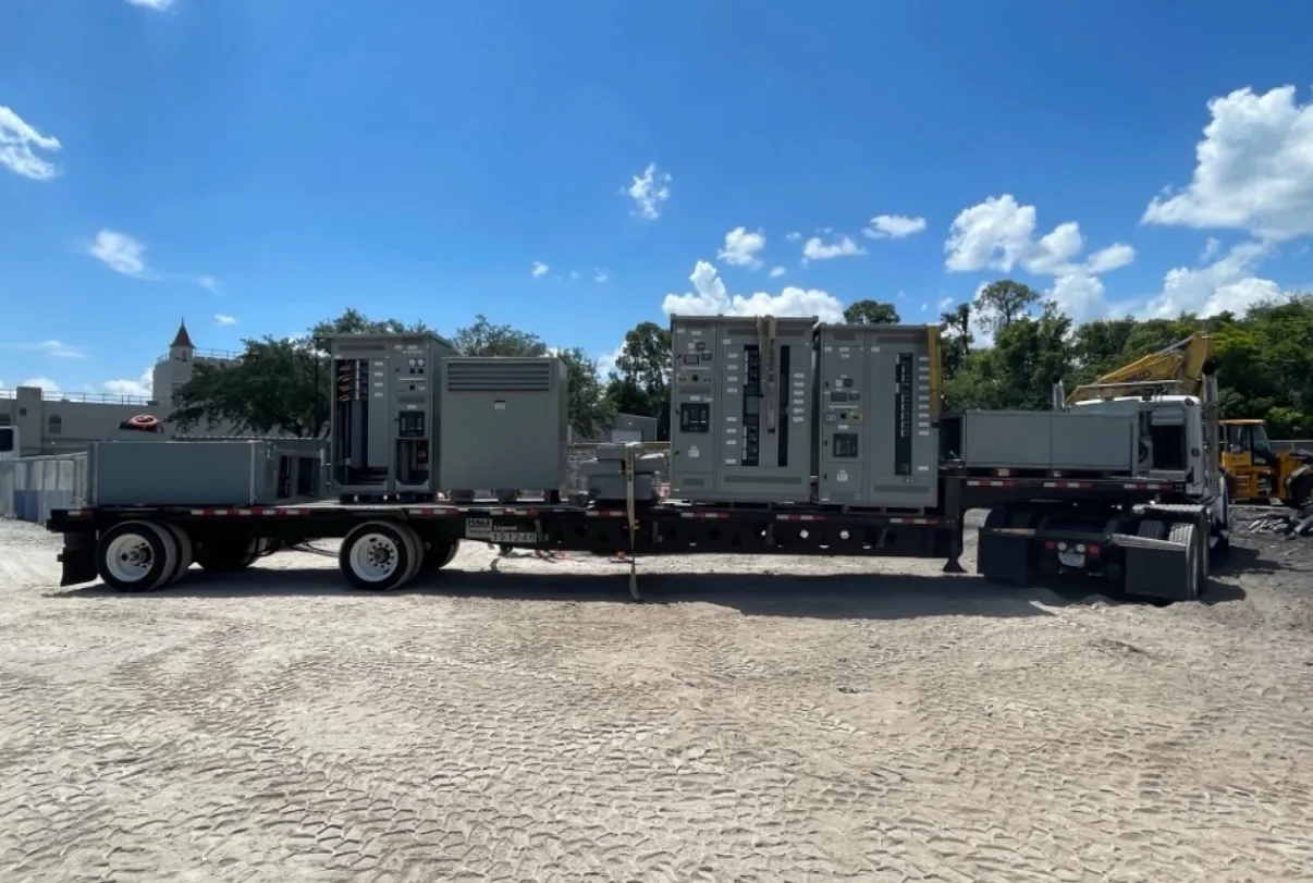
Service Entrance Switchboards for Fallon, NV Projects
A service entrance switchboard is the first major distribution assembly on the customer side of an electrical service. Its arrangement affects utility metering, the main disconnect, grounding and bonding, downstream distribution, and how protective devices respond to faults. For a Fallon project, these interfaces should be identified before the switchboard is finalized—not inferred from a generic equipment schedule. Our company manufactures new custom power-distribution equipment in the United States and supplies new assemblies to projects in Nevada and nationwide.
The switchboard design depends on the service configuration and the requirements of the serving utility and authorities having jurisdiction. A project team should establish where the utility’s responsibility ends, where customer equipment begins, and which components the utility must review or furnish. Those boundaries can influence the service section layout, metering provisions, barriers, accessible compartments and approved connection points.
Resolve Metering, Main Disconnect and Approval Interfaces
Utility metering requirements are not interchangeable from one service to another. Confirm the required metering arrangement, equipment location, compartment details, conductor routing and any utility-specific drawings or approvals. A utility may have requirements that affect switchboard dimensions or configuration, so these should be gathered early and included with the equipment inquiry. The serving utility and project engineer should confirm applicable requirements; a manufacturer’s proposed layout is not a substitute for their approval.
The main disconnect arrangement also calls for project-specific review. The design team should identify the service configuration, number and type of service disconnects, intended switching arrangement, and how the switchboard connects to downstream equipment. Main-device selection involves more than nominal current: the electrical study, available fault current, protective-device characteristics and project requirements all matter. Applicable ratings, product listings and service details must be confirmed for the proposed assembly.
Establish Fault-Current and Grounding Requirements
Available fault current at the switchboard is a key design input. It informs the required short-circuit rating and the selection and coordination of protective devices. The value must come from project-specific utility information and engineering analysis; it should not be assumed from the service voltage or a typical building schedule. Changes to transformers, conductors or upstream protection can affect the result, so the responsible engineer should verify the conditions used for equipment selection.
Service grounding and bonding likewise require coordination with the actual system and installation. The design team should identify the grounding electrode system, service bonding provisions, conductor terminations and the transition to downstream distribution. Applicable electrical codes and authority requirements depend on the project and must be reviewed by qualified professionals. Clear drawings and defined interfaces help prevent omissions between the switchboard, utility, site electrical contractor and other distribution equipment.
Match the Switchboard to Fallon Load Profiles
For a Fallon facility, provide a realistic load profile rather than only a single total-load figure. Identify existing and planned loads, their operating patterns, anticipated expansion and any loads that run simultaneously. Motor starting requirements deserve specific attention: motor size, starting method, frequency of starts and interaction with other loads can influence voltage-drop analysis, feeder and device selection, and the project’s operating objectives. The engineering team should assess these conditions before finalizing the service section.
Protective-device coordination should be defined as an objective for the project, not left as an assumption. The engineer may need to evaluate selective coordination requirements, equipment protection, continuity priorities and upstream-downstream device relationships. The appropriate result depends on the system study and applicable project criteria. A switchboard can be configured to the documented design, but it cannot independently establish the site’s coordination strategy.
Prepare a Complete Switchboard Quotation Package — Service Entrance Switchboards in Fallon, NV
A useful request for quotation includes the latest one-line diagram, service voltage and phase, calculated load information, available fault current, required equipment ratings, utility metering criteria, grounding details and relevant authority comments. Include the intended main-device configuration, downstream distribution needs, enclosure and environmental conditions, cable entry preferences, and space or access limitations. Note whether the project has defined motor-starting conditions or a protective-device coordination study. Missing or provisional information should be clearly identified so assumptions can be reviewed rather than mistaken for confirmed design inputs.
Fallon site conditions also belong in planning. Confirm the equipment location, indoor or outdoor exposure, available working area, delivery access, installation sequence and any constraints on moving the assembly into place. These details can affect enclosure selection, section arrangement and shipping configuration. Logistics and site readiness should be coordinated with the project schedule, without treating a preliminary schedule as a guaranteed delivery date.
Custom Manufacturing and Project Review — Service Entrance Switchboards in Fallon, NV
We manufacture new custom switchboards using all-American components, build the assemblies in the USA, support short lead times and ship nationwide, including to Nevada. Final configuration, ratings, applicable listings and schedule depend on the approved project documents and must be confirmed for the specific equipment. UL 891 may apply to low-voltage switchboards when the product and construction fall within its scope; it should not be assumed to cover every assembly or establish suitability for a particular service.
Before release, the project team should reconcile the utility’s metering and service requirements with the engineer’s one-line diagram, fault-current information, grounding design, load profile and coordination objectives. Qualified engineers and the relevant authorities must review the complete installation and confirm the applicable code and equipment requirements. That disciplined review gives the manufacturer a clearer basis for building a service entrance switchboard suited to the Fallon project.